Your shopping cart is empty!
Categories
- 3D Printing and Plastic peripherals (8)
- 433Mhz and Lora (9)
-
Amateur Radio (651)
- - Antenna Analyzer (12)
- - APRS (12)
- - ATU (5)
- - CW (1)
- - Digital Modes (9)
- - DMR (4)
- - Echolink (10)
- - Enclosure (13)
- - Eshail-2 (QO-100) (67)
- - GPS (8)
- - iGate (1)
- - Microcontrollers (43)
- - Microphone (1)
- - Power Supply (7)
- - Programming Cable (6)
- - QRP (9)
- - Radio interface (21)
- - Receiver (9)
- - Repeater (4)
- - RF Amplifiers (20)
- - RF Kits (19)
- - RF modules (116)
- - Rotator (1)
- - SDR (75)
- - Spectrum Analyzer (4)
- - SWR (9)
- - Transceiver (59)
- - WSPR (5)
- Antennas and Acc (320)
- Audio and Video (28)
- Bargain Box (1)
- Battery (3)
- Bluetooth (11)
- Cables (37)
- Computer Peripherals (104)
- Connectors (90)
- Data acquisition (1)
- Display (2)
- Electromechanical (25)
- Enclosure (12)
- GPS (6)
- Hardware (3)
- Home Automation (128)
- Inverter (9)
- Liquid (7)
- Lora (8)
- Microcontrollers (119)
- Modbus (3)
- MQTT (14)
- Network Radio (3)
- Networking (8)
- Power (133)
- Power supply (49)
- Radio Interface (17)
- RF Modules (142)
- ROIP (2)
- Satellite (93)
- Security (13)
- Sensor (17)
- Solar (14)
- Test and Measurements (66)
- Tools and Equipment (8)
- VOIP (10)
- Weather (1)
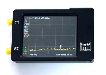
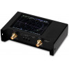
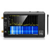
The tinySA is a small spectrum analyzer or signal generator, primarily intended for 0.1MHz to 350MHz


Price: R3,461.50
Ex Tax: R3,010.00
Ex Tax: R3,010.00
Qty:
- OR -
Add to Wish List
Add to Compare
Add to Compare

The tinySA is a small spectrum analyzer or signal generator, primarily intended for 0.1MHz to 350MHz
- Spectrum Analyzer with two inputs, high quality MF/HF/VHF input for 0.1MHZ-350MHz, lesser quality UHF input for 240MHz-960MHz or
- Signal Generator with two output, sinus output for 0.1MHz - 350MHz and square wave output for 240MHz-960MHz when not used as Spectrum Analyzer.
- Switchable resolution bandpass filters for both ranges between 2.6kHz and 640kHz
- Color display showing 290 scan points covering up to the full low or high frequency range.
- Input Step attenuator from 0dB to 31dB for the MF/HF/VHF input.
- A built-in calibration signal generator that is used for automatic self test and low input calibration.
- Connected to a PC via USB it becomes a PC controlled Spectrum Analyzer or Signal Generator
- Rechargeable battery allowing a minimum of at least 2 hours portable use
- Max input level +10dBm. Do not destroy your tinySA
- Due to the low cost and very small form factor there are certain relevant limitations.
Introduction and other videos
A short 7 minute video introducing the main features of the tinySA can be found here. Many more videos in my YouTube channel
Manual
For those that prefer to read a document instead of browsing a wiki, there are two options.
Kurt Poulson was so kind to write an extensive document explaining various aspects of the tinySA for a Danish Amatuer Radio magazine. The English version can be found here. Kurt describes the operation of the signal generator and spectrum analyzer functions and explains how to update the FW. The document contains many screen captures of example measurements.
As second options is a PDF version of the wiki, which allows for easier reading for some people, that can be found here
Main subjects covered in this wiki:
Spectrum Analyzer Introduction
- Just like an oscilloscope is used to measure and view an electronic signal versus time, a spectrum analyzer is used to measure and view an electronic signal versus frequency.
- The main specification points for a spectrum analyzer are its frequency range, the measurement resolution in this frequency range and the signal signal levels that can be displayed.
- The three important signal levels are:
- Maximum level that can be input to the spectrum analyzer without damaging the spectrum analyzer.
- Spur free maximum level is the maximum input signal to stay below for a clean, spur free display.
- Noise level is the lowest discernable signal level and this depends on the resolution bandwidth. A lower bandwidth gives a lower noise level.
-
The maximum input signal level for the tinySA is 10dBm. Signals below -30dBm should not generate spurs in low input mode and the noise level with an Resolution Bandwidth (RBW) of 10kHz is about -105dBm
-
More expensive spectrum analyzers can digitize a broad frequency range at once and,using FFT, calculate the signal over a broad frequency range. Spectrum analyzers like the tinySA use a resolution filter that is used to isolate the input power in a small frequency range. This resolution filter is swept across the desired frequency range. As the oscillator that does the sweeping and the power detector that measures the signal power require some settling time the scanning speed of the tinySA is limited. The narrower the filter the more time is needed to settle. The fastest scanning speed occurs with an RBW or 300kHz or wider and is about 2 scans per second. But with increase of the frequency span and decrease of the RBW the scanning speed decreases quickly.
-
A scan from 0MHz to 350MHz with an RBW of 10kHz takes about 2 minutes.
First Use
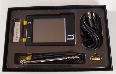
The tinySA comes in a sturdy box for protection during transport

Inside the box you find the tinySA with some accessories
- two SMA cables and a barrel connector
- an antenna with an SMA connector
- a USB-C cable
After unpacking the tinySA insert the USB cable into the tinySA and connect the cable to a USB charger or computer USB port to charge the tinySA. One hour charging should be sufficient for first usage.
After charging the USB cable can remain connected or can be disconnected.
The next steps are also explained in the video on first use
Kurt Poulsen wrote a document on the tinySA that can be found through tinySA@groups.io
Execute these steps:
- Use one of the supplied SMA cables to connect the low port to the high port.
- Power the tinySA using the tiny power switch at the top.
- Touch the screen to activate the menu system and select CONFIG and then SELF TEST. If navigation goes wrong use the BACK button or switch the tinySA Off and On to get back into a known state. If all goes well the self test will pass all tests and you can touch the screen once more to conclude.
- Leave the high and low port connected for the next step
- Next step is to do the power calibration of the LOW INPUT MODE. THis has to be done only once for one frequency and it does not have to be repeated before every measurement as the level calibration is very stable and frequency independent. From the CONFIG menu execute LEVEL CAL. The red level indicators at the top and bottom should turn white to indicate the calibration has succeeded.
Optional step:
- Doing the level calibration for the high input mode is a bit more complex but clearly explained in this video
Now the tinySA is ready to do measurements.
Connect some input signal to the low input and go back to the INPUT menu, you can select which input to use from the MODE menu, select either LOW INPUT or HIGH INPUT.
WARNING!!!. The input signal must be below +10dBm otherwise the tinySA can be damaged. Use an external attenuator when trying to measure signals with higher power levels.
WARNING!!!. Both inputs can tolerate maximum 10 Volt DC. Higher voltages may damage the inputs. Use an external DC block when measuring signals with higher DC components.
WARNING!!!. Using the supplied antenna makes the tinySA very susceptible to ESD damage or overloading. Only use the antenna with great caution. Never put the antenna close to a transmitting antenna. Never touch anything with the antenna
WARNING!!!. You can destroy the low input attenuator when you enable a high power high output signal and the high and low ports are still connected after doing a selftest or level calibration. Afways disconnect high and low inputs before enabling the high output
Use the FREQ menu to set the frequency range displayed and the LEVEL menu to set the displayed levels.
You can always go back to a defined state by clicking the PRESET button in the input menu and then LOAD STARTUP
Main Menu
These pages reflect FW version 1.3325
- PRESET loads or saves configurations.
If the saved preset contained a stored trace this will also be restored
Frequency Menu
-
There is a short video demonstrating the frequency menu
The tinySA scans its input frequency range either in start/stop mode or in center/span mode. The number of points displayed is always 290. The number of points scanned is minimum 290 but when the RBW is too small to cover the selected frequency range with 290 points additional measurements are done and accumulated into the 290 points.
- START sets the scanning to start/stop mode and sets the start frequency
- STOP sets the scanning to start/stop mode and sets the stop frequency
- CENTER sets the scanning to center/span mode and sets the center frequency
- SPAN sets the scanning to center/span mode and sets the frequency span
- ZERO SPAN sets the scanning to center/span mode, sets the span to 0Hz and sets the center frequency
- JOG STEP sets the frequency step of the jog button. Setting to zero enables an automatic definition of the step size.
- RBW sets the resolution bandwidth. Keep in mind a low RBW may increase scanning time substantially.
- SHIFT FREQ is used in combination with up/down converters and allows entering the actual START or CENTER frequency before the up/down conversion. After activation the "shifted" label is shown at the bottom of the screen. Deactivation of the shift is done by activating the menu entry again. The maximum frequency being displayed is 4.29GHz, any shift must keep the on screen frequencies below 4.29GHz.
- BACK returns to the main menu
- FREQ sets everything related to the frequency range to scan.
- LEVEL sets everything related to the level of the signals being measured.
- TRACE sets everything related to a trace
- DISPLAY controls various aspects of how the signals are being displayed.
- MARKER controls the markers on the display.
- MEASURE helps to quickly set the tinySA for certain measurements.
- CONFIG activates the configuration menu.
- MODE activates the mode switching menu.
Level Menu
There is a short video demonstrating the level menu
Various attributes of the display can be adapted
- REF LEVEL sets the level in selected unit of the top of the display. The ref level can be set to AUTOMATIC and is automatically adjusted to keep the strongest signals just below the top of the screen.
- SCALE/DIV sets the amount of selected unit per division of the display.
- ATTENUATE sets the amount of attenuation applied to the low input/output. The range is 0 to 31 dB. There is no settable attenuator in high mode. When set to AUTOMATIC the attenuation tries to keep the strongest signals minus the attenuation below -25dBm.
- UNIT selects the display unit. dBm, dBmV, dBuV, Volt or Watt
- EXTERN GAIN sets the level offset in dB caused by an external amplifier or attenuator. Default is 0. Example: For an external 20dB attenuator set to -20
- TRIGGER selects the trigger mode
- LISTEN puts the tinySA in Listen mode at the frequency of the current active marker. The scanning stops and audio is available at the indicated solder pad. The user interface keeps working so you can change the listen frequency while in Listen mode.
- BACK returns to the main menu
To enable the listening you have to do a HW modification of the tinySA as described here
Trace Menu
There is a short video demonstrating the trace menu
- TRACE x selects the trace to act on. One of three traces can be selected.
- ENABLE enables the display of the selected trace
- FREEZE holds the updating of the selected trace. This is used to create static traces
- CALC selects various calculation options over time such as averaging or max hold.
- NORMALIZE stores the current trace in trace 3 as a reference and subtract trace 3 from the currently selected trace. It is not possible to normalize trace 3.
- SUBTRACT enables the selection of a trace to subtract from the currently selected trace. It is not possible to select the currently selected trace for subtraction.
- COPY->TRACE copies the current trace to a selected trace. It is not possible to copy a trace to itself
- BACK returns to the input menu
Display Menu
There is a short video demonstrating the display menu
- PAUSE SWEEP pauses the scanning
- WATERFALL displays the power level over time in a waterfall map. A second click enlarges the waterfall. Click again to disable. The waterfall moves per scan and displays the last 40 (small mode) or 80 (large mode) scans.
- SWEEP TIME sets the minimum time for a complete sweep in seconds. Using the 'm' button on the keypad it is possible to specify the sweep time in milliseconds. Setting the sweep time to zero enables the fastest sweep. Setting a sweep time below the fastest sweep time has no impact.
- SWEEP POINTS allows setting the number of sweep points to 51, 101, 145 or the default of 290. Reducing the sweep points will only lead to a reduction of sweep time if the RBW using the reduced number of sweep points is below 600kHz.
- SWEEP ACCURACY menu contains various settings on how to sweep the selected frequency or time span.
- BACK returns to the input menu
Marker Menu
Markers are used to display the value of signals. One marker is active and marked with an inverted number.
- MODIFY MARKER allows selecting a marker and shows a submenu to modify the MARKER TYPE or to delete the marker.
- MARKER OPS allows setting the frequency display range based on the active marker
- SEARCH MARKER allows positioning a non-tracking marker on signal maximum or minimum. This can also be done using the jog button or by dragging the marker.
- RESET MARKERS resets all markers to the default state
- BACK returns to the input menu
Marker 1 is by default enabled and has the TRACKING attribute and is thus automatically positioned at the largest signal in the scan. The active marker can be moved with the jog switch. Any marker can be moved by dragging the marker to a new position. The active marker can also be selected by touching the related marker info at the to of the screen.
First Measurement Menu
The measurement menu provides quick presets and data entering for certain type of measurements.
- OFF switches of any measurement related setting and behavior and returns the tinySA to regular operation
- HARMONIC switches to a marker configuration for measuring the level of harmonics of a signal
- OIP3 switches to a marker configuration for measuring the Output IP3 level of a signal
- PHASE NOISE switches to a marker configuration for measuring phase noise of a signal
- SNR set three markers, a tracking marker and two delta markers at the specified distance to the tracking marker
- -3dB WIDTH sets three markers, a tracking marker and two delta markers at the -3dB levels versus the tracking marker and the delta frequency of the two delta markers is calculated
- MORE moves to the second measure menu
- BACK moves back to the input menu
Configuration menu
The configuration menu can be used to update various settings and to test or calibrate the tinySA
- TOUCH activates the touch sub menu
- TOUCH CAL enables the calibration of the touch panel. The results are stored in NVM.
- TOUCH TEST is used to verify touch calibration.
- SELF TEST is used after a cable is used to connect the low and high input/output. The progress is displayed and you need to touch the display after each failing test and at the end of the test.
- LEVEL CAL is used to calibrate the power measurement levels. A new menu appears and you will be asked to to connect the low and high input/output. After connecting the cable, activate CALIBRATE. The calibration can be reset by RESET CALIBRATION. At the end of the calibration switch of the tinySA. After switching on again the numbers indicating the power levels should be in white to indicate the power reading is calibrated. An uncalibrated state is indicated with red level indicators. The level calibration data is stored in the leveloffset configuration variable.
- VERSION shows the SW version information.
- SPUR REMOVAL activates the two spur removal mechanisms. Below 190MHz the above and below IF are used to identify spurs and above 190MHZ the IF is shifted.
- EXPERT CONFIG activates the expert configuration menu
- ->DFU switches the tinySA to firmware upgrade mode.
- BACK moves back to the input menu.
Mode Menu
The mode menu allows switching to one of the four operating modes of the tinySA and to activate the calibration output. Switching mode will reset all users settings to the default values for the selected mode. Returning to a currently active mode will not changes any settings.
- LOW INPUT activates the 0.1-350MHz input mode
- HIGH INPUT activates the 240MHz-960MHz input mode
- LOW OUTPUT activates the 0.1-350MHz output mode
- HIGH OUTPUT activates the 240MHz-960MHz output mode
- CAL OUTPUT controls the build in calibration reference generator. The output of the reference generator is connected to the high mode input/ouput. The output frequency can be 1,2,4,10,15 and 30MHz and the output level of the fundamental at 30MHz is -25dBm
- BACK returns to the current active mode.
Legal stuff
The name tinySA and the tinySA logo is a registered trademark owned by us. Nobody else is allowed to use the name tinySA for any spectrum analyzer product without written permission.
Write a review
Your Name:Your Review: Note: HTML is not translated!
Rating: Bad Good
Enter the code in the box below:

Powered By OpenCart
Giga Technology © 2025
Giga Technology © 2025