Shopping Cart
0 item(s) - R0.00- 3D Printing and Plastic peripherals (8)
- 433Mhz and Lora (9)
-
Amateur Radio (651)
- - Antenna Analyzer (12)
- - APRS (12)
- - ATU (5)
- - CW (1)
- - Digital Modes (9)
- - DMR (4)
- - Echolink (10)
- - Enclosure (13)
- - Eshail-2 (QO-100) (67)
- - GPS (8)
- - iGate (1)
- - Microcontrollers (43)
- - Microphone (1)
- - Power Supply (7)
- - Programming Cable (6)
- - QRP (9)
- - Radio interface (21)
- - Receiver (9)
- - Repeater (4)
- - RF Amplifiers (20)
- - RF Kits (19)
- - RF modules (116)
- - Rotator (1)
- - SDR (75)
- - Spectrum Analyzer (4)
- - SWR (9)
- - Transceiver (59)
- - WSPR (5)
- Antennas and Acc (320)
- Audio and Video (28)
- Bargain Box (1)
- Battery (3)
- Bluetooth (11)
- Cables (37)
- Computer Peripherals (104)
- Connectors (90)
- Data acquisition (1)
- Display (2)
- Electromechanical (25)
- Enclosure (12)
- GPS (6)
- Hardware (3)
- Home Automation (128)
- Inverter (9)
- Liquid (7)
- Lora (8)
- Microcontrollers (119)
- Modbus (3)
- MQTT (14)
- Network Radio (3)
- Networking (8)
- Power (133)
- Power supply (49)
- Radio Interface (17)
- RF Modules (142)
- ROIP (2)
- Satellite (93)
- Security (13)
- Sensor (17)
- Solar (14)
- Test and Measurements (66)
- Tools and Equipment (8)
- VOIP (10)
- Weather (1)
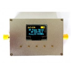
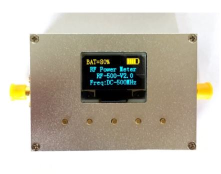
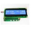
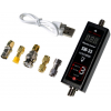
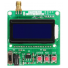
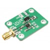
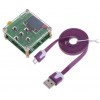
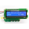
1PC RF power meter V2.0 RF power attenuation value can be set
Ex Tax: R3,526.00
Add to Compare
1PC RF Power meter V2.0. RF power attenuation value can be set.
Product Overview:
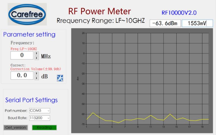
The RF-Power-Meter-V2.0 series is a high-performance, low-cost portable RF power meter. The series consists of three series, namely RF500V2.0 (500MHz), RF3000V2.0 (3GHz), RF10000 (10GHz), equipped with a 0.96-inch 128x64-pixel OLED display and a 500mAh lithium battery, providing 5V power supply and charging through micro-USB . Easy to use, compact, easy to carry, stable performance, high accuracy, presetable offset, wide dynamic range, and fast measurement speed. The software packaged with the power meter allows the user to configure the power meter on the PC side and make it easy to record (with a curve display) and share data.
The host computer and instructions for use to download, copy, open in the webpage, Baidu cloud link
Links: https://pan.baidu.com/s/1dF6dHo1 Password: 18bp Power Meter V2.0 PC software, instructions for use
Product application:
● Calibration of RF instrumentation equipment;
● Testing and maintenance of radio frequency equipment;
● Measurement of standing wave ratio of RF circuit (adding feedback bridge);
● Measurement of return loss of RF circuits;
● Interference detection between wireless communication devices;
● RSSI (received signal strength indication) and transmit power level detection;
● Stepper attenuator performance evaluation;
● amplifier gain and network attenuation measurements;
● Measurement of forward power and reflected power in a directional coupler;
● Power measurement of GSM signals using GMSK modulation*;
Product technical indicators:
1. Measuring power range -75 to +15 dBm (different model frequency range is not the same)
2. Measuring power resolution ±0.1 dBm
3, measuring frequency range 100K ~ 10000 MHz (different types of frequency range is not the same)
4, input impedance 50Ω
5, dynamic range> 90dB
6, operating voltage 5VDC (powered by micro-USB)
7, working current <50 mA
8, Lithium battery capacity: 500mAh
9, charge current: 500mA
10, size 68*48*18 mm (length X width X height)
Operating Instructions:
1. Power supply: Connect the power supply via micro-USB (signal source, computer, charging treasure, etc.).
2. Power switch: next to USB, switch left to switch on, dial right to switch off.
3. Input: Connect the RF signal through SMA1 interface, SMA2 is the detection voltage output for customers' secondary development.
4. After powering on, press the "OK S3" key to initialize the power meter.
5. press S1 to change the cursor position (left)
6. Press key S5 to change the position of the cursor (right shift)
7. Press button S2 to change the data of the cursor
8. Press key S4 to change the data of the cursor
After entering the system, the cursor indicates the selected digit. At this time, the up and down keys can modify the value of the selected digit. When the cursor is in the last position (or first position) of the selected item, pressing the right (or left) key switches the selected item. When the parameters are set, press the middle OK key to make the settings take effect.
Note: For the method of using the power meter connection computer in combination with the host computer software, please refer to the “Upper Machine Instructions”.
Offset: Provides offset selection for both positive and negative signs.
Here are three common situations where you need to preset offsets:
1. The signal is too large. An attenuator is added between the signal source and the power meter. The offset is set as the attenuation of the attenuator. The symbol is “positive”.
2. The signal is too small. Add an amplifier between the signal source and the power meter. Set the gain to the gain of the amplifier. The sign is “negative.”
3. The signal has a loss (attenuation) between the source and the power meter. The offset is set to the attenuation of the signal and the sign is “positive”.
Write a review
Your Name:Your Review: Note: HTML is not translated!
Rating: Bad Good
Enter the code in the box below:
Giga Technology © 2025

