Shopping Cart
0 item(s) - R0.00- 3D Printing and Plastic peripherals (8)
- 433Mhz and Lora (9)
-
Amateur Radio (651)
- - Antenna Analyzer (12)
- - APRS (12)
- - ATU (5)
- - CW (1)
- - Digital Modes (9)
- - DMR (4)
- - Echolink (10)
- - Enclosure (13)
- - Eshail-2 (QO-100) (67)
- - GPS (8)
- - iGate (1)
- - Microcontrollers (43)
- - Microphone (1)
- - Power Supply (7)
- - Programming Cable (6)
- - QRP (9)
- - Radio interface (21)
- - Receiver (9)
- - Repeater (4)
- - RF Amplifiers (20)
- - RF Kits (19)
- - RF modules (116)
- - Rotator (1)
- - SDR (75)
- - Spectrum Analyzer (4)
- - SWR (9)
- - Transceiver (59)
- - WSPR (5)
- Antennas and Acc (320)
- Audio and Video (28)
- Bargain Box (1)
- Battery (3)
- Bluetooth (11)
- Cables (37)
- Computer Peripherals (104)
- Connectors (90)
- Data acquisition (1)
- Display (2)
- Electromechanical (25)
- Enclosure (12)
- GPS (6)
- Hardware (3)
- Home Automation (128)
- Inverter (9)
- Liquid (7)
- Lora (8)
- Microcontrollers (119)
- Modbus (3)
- MQTT (14)
- Network Radio (3)
- Networking (8)
- Power (133)
- Power supply (49)
- Radio Interface (17)
- RF Modules (142)
- ROIP (2)
- Satellite (93)
- Security (13)
- Sensor (17)
- Solar (14)
- Test and Measurements (66)
- Tools and Equipment (8)
- VOIP (10)
- Weather (1)
Softrock 6m/4m/2m RX Ensemble Receiver Kit
Ex Tax: R1,151.60
Add to Compare
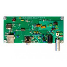
SoftRock 6m/4m/2m RX Ensemble Receiver Kit
The Softrock kit is one of the best and is a very good SDR. The performance is very good compared to the expensive Amateur radios.
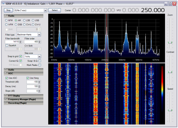
The free SDR software is also very mature and there functionality is even better that the expensive Amateur Radios.
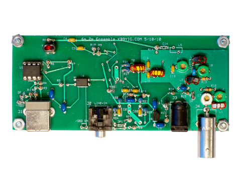
The SoftRock 6m/4m/2m RX Ensemble Receiver Kit includes the components for building a VHF receiver for 6m, 4m, or 2m.
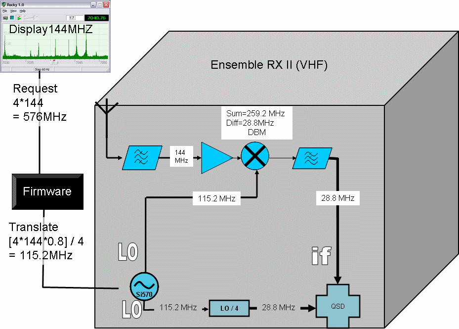
The design consists of an RF amplifier stage into a diode mixer stage whose output is transformer-coupled into a QSD circuit. The Si570 is used as a clock source for both the diode mixer and also the QSD circuit. The center frequency is related to the Si570 output frequency by the relationship Si570 frequency +/- (Si570 frequency)/4. (See page 2 of schematic for details.)
The circuit board measures 4.5 inches by 2.0 inches.
NOTE: This product is a kit. The product photo shows what it should look like once assembled. A sound card with stereo line-in connector and a computer running SDR software are required to operate this radio.
Background
This kit, based upon a design by Jan G0BBL, and implemented and distributed by Tony KB9YIG, extends the Ensemble II RX kit , replacing the front-end with a circuit that down-converts VHF signals in the 2m, 4m or 6m bands to HF signals that can be received in the RX's "back-end" (which is essentially the Ensemble II RX).
The parts provided in this kit permit the builder to select which of the major VHF bands to implement; all the parts for all the options are included in the kit. Band-specific parts are identified throughout the documentation; the builder makes his/her choice at build-time.
The builder will find invaluable information at the website of Fred PE0FKO, especially the setup of the software and firmware, as documented in the excellent users manual from Bob G8VOI.
For kit building information, please see: WB5RVZ.
Background
This kit, based upon a design by Jan G0BBL, and implemented and distributed by Tony KB9YIG, extends the Ensemble II RX kit , replacing the front-end with a circuit that down-converts VHF signals in the 2m, 4m or 6m bands to HF signals that can be received in the RX's "back-end" (which is essentially the Ensemble II RX).
The parts provided in this kit permit the builder to select which of the major VHF bands to implement; all the parts for all the options are included in the kit. Band-specific parts are identified throughout the documentation; the builder makes his/her choice at build-time.
The builder will find invaluable information at the website of Fred PE0FKO, especially the setup of the software and firmware, as documented in the excellent users manual from Bob G8VOI.
Block Diagram
Relationship to the Ensemble RX II HF/LF Kit
This kit reuses a large percentage of the design of the Ensemble II RX (HF/LF) kit. Refer to that kit's home page for a theory discussion on the radio. This kit reuses the following stages, basically untouched, from the Ensemble II RX:
- Power Supply
- USB Power Supply
- Local Oscillator and Control
- Quadrature Clock Generator
- Quadrature Sampling Detector
- Operational Amplifiers
The main difference is in the RF and COntrol stage, which is based upon an earlier design for a VHF add-on board for the Softrock V9.0 RX. The theory of the Software Designed Radio can be gleaned from the Ensemble II RX documentation. Here, we will concentrate on the differences (where the RF/Auto BPF functionality is replaced with the stage described in the following paragraphs.
RF Input.
This discussion will use, as an example, a 144 MHZ signal that will be down-converted to an IF in the apporpriate HF frequency range for detection in the "standard SDR" stages.
The incoming signal from the Antenna terminal (or, via a jumper wire from J1/P100 Pin 1) , e.g., 144MHz, is filtered, then pre-amplified by Q1 and fed to a double-balanced mixer, U7.
Mixing
U7 also receives a Local Oscillator signal via from the Si570's (U3's) LO Out. This local oscillator signal must be at a frequency (in our example, 115.2 MHz) which, when mixed with the incoming 144 MHz signal, will produce both a difference (144 - 115.2 = 28.8MHz) and the sum (144 + 115.2MHz = 259.2MHz). Fred PE0FKO's Firmware handles this translation. See notes below on how to program the AVR (U1) to result in an IF frequency that is equal to the Ensemble's quadrature clock frequency.
Intermediate Frequency (IF)
The output of the mixer at U7's pin 2 is filtered to remove the sum (image frequency). The (difference) IF is transformed into two anti-phase signals by T2 and fed to the Ensemble's Quadrature Sampling Detector via T2's secondaries and the coupling resistors R16 and R17. At this point, the radio operates pretty much the same way that the HF/LF versions of the Ensemble II RX operate.
Tuning
Tuning the band is then done in the Ensemble VHF RX on signals centering around the quadrature clock frequency (converted in software to the corresponding VHF frequency display values).
Calculating the LO Frequencies
Care must be taken to calculate the LO frequencies so as to arrive at an IF that is exactly equal to the quadrature clock frequency. This is done using a multiplier factor that is specific to the band. This multiplier for 2m is 0.8; for 4m and 6m it is (4/3).
Calculation of LO frequency for 2m band
To determine the correct frequency for the SI570 for the 2m band, multiply the Desired VHF frequency by 0.8 - see following table:
| VHF | LO=0.8*VHF | Quad = LO/4 | IF=VHF-(4*quad) | Shortcut = 0.2*VHF |
|---|---|---|---|---|
| 144.00 | 115.20 | 28.80 | 28.80 | 28.80 |
| 145.00 | 116.00 | 29.00 | 29.00 | 29.00 |
| 146.00 | 116.80 | 29.20 | 29.20 | 29.20 |
| 147.00 | 117.60 | 29.40 | 29.40 | 29.40 |
| 148.00 | 118.40 | 29.60 | 29.60 | 29.60 |
Calculation of LO frequency for 6m band
To determine the correct frequency for the SI570 for the 6m band, multiply the Desired VHF frequency by (4/3)- see following table:
| VHF | LO=(4/3)*VHF | Quad = LO/4 | IF = VHF - (4*quad) | Shortcut = (1/3)*VHF |
|---|---|---|---|---|
| 50.00 | 66.67 | 16.67 | 16.67 | 16.67 |
| 51.00 | 68.00 | 17.00 | 17.00 | 17.00 |
| 52.00 | 69.33 | 17.33 | 17.33 | 17.33 |
| 53.00 | 70.67 | 17.67 | 17.67 | 17.67 |
| 54.00 | 72.00 | 18.00 | 18.00 | 18.00 |
Calculation of LO frequency for (EU) 4m band
To determine the correct frequency for the SI570 for the (EU) 4m band, multiply the Desired VHF frequency by (4/3)- see following table:
| VHF | LO=(4/3)*VHF | Quad = LO/4 | IF = VHF - (4*quad) | Shortcut = (1/3)*VHF |
|---|---|---|---|---|
| 70.00 | 93.33 | 23.33 | 23.33 | 23.33 |
| 70.15 | 93.53 | 23.38 | 23.38 | 23.38 |
| 70.30 | 93.73 | 23.43 | 23.43 | 23.43 |
| 70.50 | 94.00 | 23.50 | 23.50 | 23.50 |
I/Q Swapping
For the bands below 2m (i.e., 6m and, in the EU, 4m) the LO frequency will be higher than the desired VHF frequency. This calls for swapping the I and Q leads from their normal ring/tip orientation (this can be done by appropriately installing the jumper wires in theoperational amplifier stage.
Project Schematic
(Resistor testpoints (hairpin, top, or left-hand lead), as physically installed on the board, are marked in the schematic with red dots)

(above schematic has clickable areas that can be used for navigation)
Project Bill of Materials
Project Expert's (terse) Build Notes
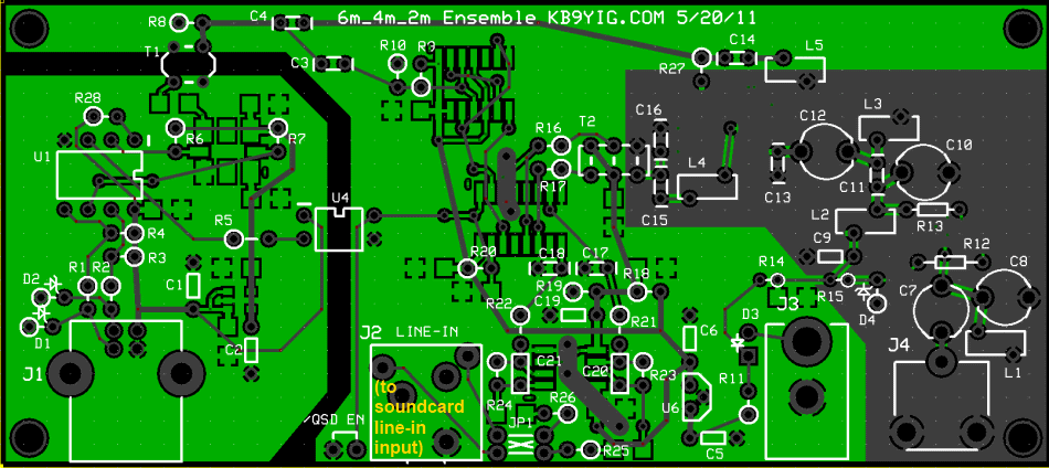
Board Top
Board Bottom
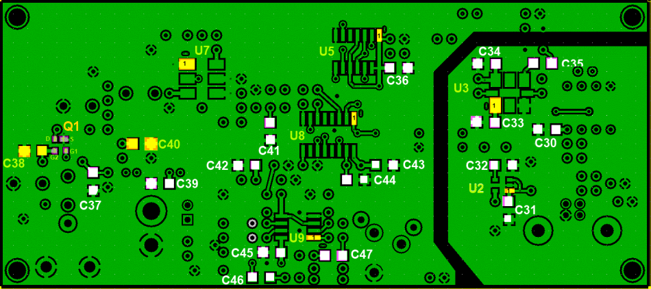
Schematics
Latest schematic sheets are at:
Build Procedure
- Stuff all the parts
- test it all
Project Detailed Build Notes
For the non-expert builders among us, this site takes you through a stage-by-stage build of the kit. Each stage is self-contained and outlines the steps to build and test the stage. This ensures that you will have a much better chance of success once you reach the last step, since you will have successfully built and tested each preceding stage before moving on to the next stage.
Each stage is listed below, in build order, and you can link to it by clicking on its name below (or in the header and/or footer of each web page).
- Inventory the Bill of Materials
- Build and Test the Power Supply Stage
- Build and Test the USB Power Supply Stage
- Build and Test the Local Oscillator/Control Stage
- Build and Test the Quadrature Clock Generator Stage
- Build and Test the RF Front End Stage
- Build and Test the Quadrature Sampling Detector Stage
- Build and Test the Operational Amplifiers Stage
- Build and Test the External Connections Stage
- Build and Test the Software Setup Stage
Schematic
Bill of Material
Software Installation
Windows SDR# software is avalible here
Linux Quisk software.
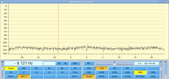
Quisk is avalibel here
Write a review
Your Name:Your Review: Note: HTML is not translated!
Rating: Bad Good
Enter the code in the box below:
Giga Technology © 2025

