Shopping Cart
0 item(s) - R0.00- 3D Printing and Plastic peripherals (8)
- 433Mhz and Lora (9)
-
Amateur Radio (651)
- - Antenna Analyzer (12)
- - APRS (12)
- - ATU (5)
- - CW (1)
- - Digital Modes (9)
- - DMR (4)
- - Echolink (10)
- - Enclosure (13)
- - Eshail-2 (QO-100) (67)
- - GPS (8)
- - iGate (1)
- - Microcontrollers (43)
- - Microphone (1)
- - Power Supply (7)
- - Programming Cable (6)
- - QRP (9)
- - Radio interface (21)
- - Receiver (9)
- - Repeater (4)
- - RF Amplifiers (20)
- - RF Kits (19)
- - RF modules (116)
- - Rotator (1)
- - SDR (75)
- - Spectrum Analyzer (4)
- - SWR (9)
- - Transceiver (59)
- - WSPR (5)
- Antennas and Acc (320)
- Audio and Video (28)
- Bargain Box (1)
- Battery (3)
- Bluetooth (11)
- Cables (37)
- Computer Peripherals (104)
- Connectors (90)
- Data acquisition (1)
- Display (2)
- Electromechanical (25)
- Enclosure (12)
- GPS (6)
- Hardware (3)
- Home Automation (128)
- Inverter (9)
- Liquid (7)
- Lora (8)
- Microcontrollers (119)
- Modbus (3)
- MQTT (14)
- Network Radio (3)
- Networking (8)
- Power (133)
- Power supply (49)
- Radio Interface (17)
- RF Modules (142)
- ROIP (2)
- Satellite (93)
- Security (13)
- Sensor (17)
- Solar (14)
- Test and Measurements (66)
- Tools and Equipment (8)
- VOIP (10)
- Weather (1)
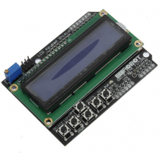
Keypad Shield Blue Backlight For Arduino LCD 1602 Board
Ex Tax: R174.00
Add to Compare
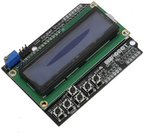
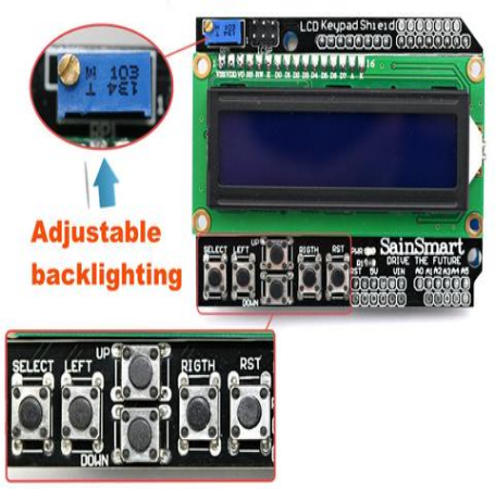
Keypad Shield Blue Backlight For Arduino LCD 1602 Board.
Description:
Keypad Shield Blue Backlight For Arduino Robot LCD 1602 Board
Brand new and high quality.
This is a basic 16 character by 2 line black-on-green display.
Utilizes the extremely common HD44780 parallel interface chipset.
Interface code is freely available.
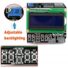
Blue Backlight with white words.
Uses 4 Bit Arduino LCD Library.
Size:8cm x 5.9cm - 3.15inch x 2.32inch.
Software Library
Package included:
1 x Arduino LCD1602 Keypad Shield for Duemilanove Freeduino.
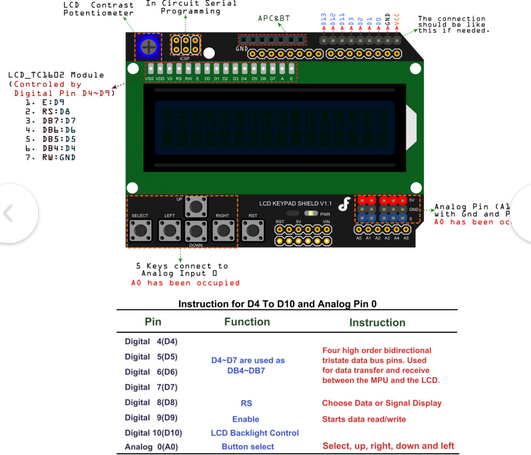
Which Pins?
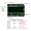
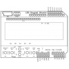
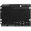
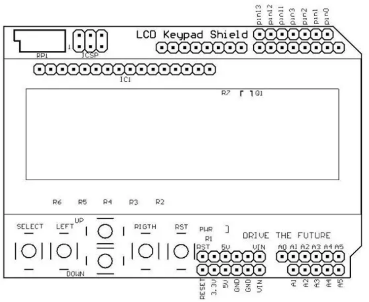
As shown on the picture, the LCD module is soldered onto a circuit board / shield – so the next step is to map the pin-out from the display module (typically, the display module will have labels printed on the pins on its header) and to the pins on the shield that connect to the Arduino.
For the other 5 buttons, they all map to one pin – to the analog pin A0, which when read will give different values depending on which button is pressed. This is achieved by a circuit of resistors connected like so, and A0 measuring the potential as indicated on the diagram:

I’m not including the values of the resistors, as that’s really not interesting for what we’re doing: writing a sketch using the keypad. What is interesting is what values one read from A0 when a button is pressed. To this end, I use a small sketch like this, which simply writes the value read on A0 on the (in this case) LCD:
Exsample Codes to display ke predd on LCD
#include <LiquidCrystal.h>
#define btnRIGHT 0
#define btnUP 1
#define btnDOWN 2
#define btnLEFT 3
#define btnSELECT 4
#define btnNONE 5
#define btnUNKNOWN 6
int readkeypad(){
int adc_key_in = analogRead(0); //
int ret = btnUNKNOWN;
if (adc_key_in < 50) ret = btnRIGHT;
if ((adc_key_in > 500) && (adc_key_in < 1150)) ret = btnNONE;
if ( (adc_key_in > 120) && (adc_key_in < 150) ) ret = btnUP;
if ( (adc_key_in > 250) && (adc_key_in < 350) ) ret = btnDOWN;
if ( (adc_key_in > 450) && (adc_key_in < 500) ) ret = btnLEFT;
if ( (adc_key_in > 700) && (adc_key_in < 750) ) ret = btnSELECT;
return ret;
}
// Just for ease of displaying
const char *button[7] ={"Right ", "Up ", "Down ", "Left ", "Select ", " ", "??????"};
LiquidCrystal lcd(8, 9, 4, 5, 6, 7);
void setup() {
lcd.begin(16, 2);
}
void loop() {
lcd.setCursor(0, 0);
lcd.print("Button Pressed:");
lcd.setCursor(0, 1);
lcd.print(button[readkeypad()]);
}
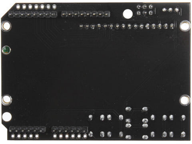
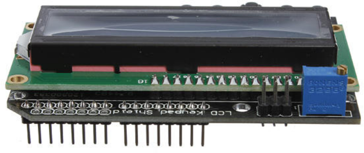
Details pictures :
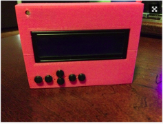
Here is an exsample of a 3D printed enclosure details se details in link below
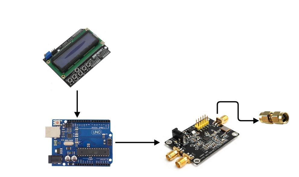
Here is an example of how this unit can be used in conjunction with Local oscillator 35Mhz to 4Ghz.
Write a review
Your Name:Your Review: Note: HTML is not translated!
Rating: Bad Good
Enter the code in the box below:
Giga Technology © 2025

