Your shopping cart is empty!
Categories
- 3D Printing and Plastic peripherals (8)
- 433Mhz and Lora (9)
-
Amateur Radio (651)
- - Antenna Analyzer (12)
- - APRS (12)
- - ATU (5)
- - CW (1)
- - Digital Modes (9)
- - DMR (4)
- - Echolink (10)
- - Enclosure (13)
- - Eshail-2 (QO-100) (67)
- - GPS (8)
- - iGate (1)
- - Microcontrollers (43)
- - Microphone (1)
- - Power Supply (7)
- - Programming Cable (6)
- - QRP (9)
- - Radio interface (21)
- - Receiver (9)
- - Repeater (4)
- - RF Amplifiers (20)
- - RF Kits (19)
- - RF modules (116)
- - Rotator (1)
- - SDR (75)
- - Spectrum Analyzer (4)
- - SWR (9)
- - Transceiver (59)
- - WSPR (5)
- Antennas and Acc (320)
- Audio and Video (28)
- Bargain Box (1)
- Battery (3)
- Bluetooth (11)
- Cables (37)
- Computer Peripherals (104)
- Connectors (90)
- Data acquisition (1)
- Display (2)
- Electromechanical (25)
- Enclosure (12)
- GPS (6)
- Hardware (3)
- Home Automation (128)
- Inverter (9)
- Liquid (7)
- Lora (8)
- Microcontrollers (119)
- Modbus (3)
- MQTT (14)
- Network Radio (3)
- Networking (8)
- Power (133)
- Power supply (49)
- Radio Interface (17)
- RF Modules (142)
- ROIP (2)
- Satellite (93)
- Security (13)
- Sensor (17)
- Solar (14)
- Test and Measurements (66)
- Tools and Equipment (8)
- VOIP (10)
- Weather (1)
Si5351A Breakout Board with crystal reference oscillator (8 kHz to 160 MHz) 3 outputs
 3 outputs")
 3 outputs")
Price: R70.15
Ex Tax: R61.00
Ex Tax: R61.00
Qty:
- OR -
Add to Wish List
Add to Compare
Add to Compare

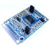
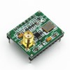
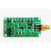
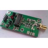
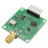
Si5351A Breakout Board 8 kHz to 160 MHz.
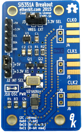
A handy way to use the Si5351A clock generator IC in your RF and microcontroller projects.
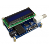
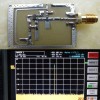
The Silicon Labs Si5351A is a fantastic clock generator IC with some features that you won't see anywhere else. It can generate three independent output signals between 8 kHz and 160 MHz (there are some limitations, see Constraints below), using only a simple 25 MHz crystal reference oscillator. Each output can be independently tuned, switched on or off, and have a variable drive level selected. Using an Arduino and a library provided by us, you may control almost every parameter of the IC. The Si5351A is very useful in a variety of applications, such as wide-range VFOs (and can also simultaneously provide a BFO signal), handy signal source, beacon transmitter, or any other project where a stable and tuneable signal is needed.
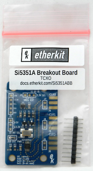
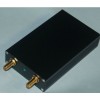
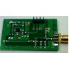
The Etherkit Si5351A Breakout Board makes it convenient to use the Si5351A with your Arduino or other favorite microcontroller. While the Si5351A is a +3.3 V IC, our board provides a low-dropout voltage regulator and level conversion circuitry so that it can be used with either 3.3 V or 5 V controllers. The three outputs are brougt out to pads which accept SMA female end launch connectors (sold separately) and also to 0.1" headers. You may choose a standard 25 MHz crystal reference oscillator, or an optional high-stability 25 MHz TCXO reference oscillator.
Specifications
- All SMT components assembled, 0.1" headers included separately
- Fully tested
- Output frequency range: 8 kHz to 160 MHz (see Constraints below)
- Number of outputs: 3
- Output impedance: 50 Ω
- Output drive levels: 2 mA, 4 mA, 6 mA, 8 mA (into 50 Ω)
- Power supply: +3.3 V or +5 V
- Interface: I2C (on a 0.1" header)
- Output jacks: 0.1" header or optional SMA female end launch
- PCB material: high quality 1.6 mm double-sided FR4 with soldermask and ENIG coating
- PCB dimensions: 30 mm x 50 mm
- RoHS Compliant
Constraints
Two multisynths cannot share a PLL with when both outputs are < 1.024 MHz or >= 112.5 MHz. This means that you may only have two outputs under those conditions.
Documentation
Schematics
You will find all of the official documentation at the Etherkit Documentation Wiki.
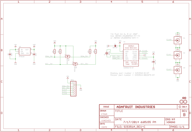
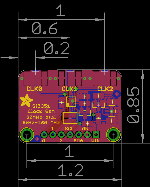
Diagram
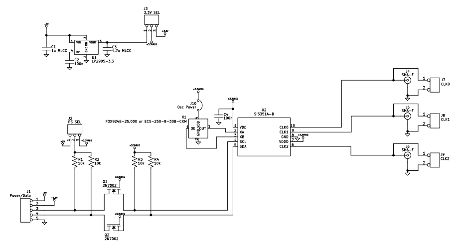
Part list
Si5351A Breakout Board BOM
Etherkit
11 Apr 2016

| Part (marking)                  | Qty  | Ref                            | P/N
======================================================================================================
Capacitors (size 0805)
| 100n                              2      C2, C4
| 1u MLCC                           1      C1
| 4.7u MLCC                         1      C3

Connectors
| 0.1 inch jumper                   2                                       3M 969102-0000-DA
| 0.1 inch header - 3 pins          2      J2, J3
| 0.1 inch header - 5 pins          1      J1

Crystals/Oscillators
| 25 MHz crystal                    1      X1                               ECS ECS-250-8-30B-CKM
OR
| 25 MHz TCXO                       1      X1                               Abracon ASTX-H11-25.000MHZ-T
                                                                              (From 11 Apr 2016, from S/N 001126)
                                                                            Fox FOX924B-25.000
                                                                              (Until 10 Apr 2016, to S/N 001125)

Semiconductors
| 2N7002                            2      Q1, Q2                           NXP 2N7002P,215

Resistors & Trimmers (0.125 W size 0805)
| 10k                               4      R1, R2, R3, R4

ICs
| LP2985-3.3                        1      U1                               TI LP2985-33DBVR
| Si5351A-B                         1      U2                               SiLabs SI5351A-B-GT

Miscellaneous
| PCB                               1

Optional
| SMA female end launch             3      J7, J8, J9
Sample code.
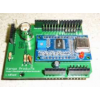
Note Colour may differ
Write a review
Your Name:Your Review: Note: HTML is not translated!
Rating: Bad Good
Enter the code in the box below:
Powered By OpenCart
Giga Technology © 2025
Giga Technology © 2025