Shopping Cart
0 item(s) - R0.00- Frequency
- 3D Printing and Plastic peripherals (8)
- 433Mhz and Lora (9)
-
Amateur Radio (651)
- - Antenna Analyzer (12)
- - APRS (12)
- - ATU (5)
- - CW (1)
- - Digital Modes (9)
- - DMR (4)
- - Echolink (10)
- - Enclosure (13)
- - Eshail-2 (QO-100) (67)
- - GPS (8)
- - iGate (1)
- - Microcontrollers (43)
- - Microphone (1)
- - Power Supply (7)
- - Programming Cable (6)
- - QRP (9)
- - Radio interface (21)
- - Receiver (9)
- - Repeater (4)
- - RF Amplifiers (20)
- - RF Kits (19)
- - RF modules (116)
- - Rotator (1)
- - SDR (75)
- - Spectrum Analyzer (4)
- - SWR (9)
- - Transceiver (59)
- - WSPR (5)
- Antennas and Acc (320)
- Audio and Video (28)
- Bargain Box (1)
- Battery (3)
- Bluetooth (11)
- Cables (37)
- Computer Peripherals (104)
- Connectors (90)
- Data acquisition (1)
- Display (2)
- Electromechanical (25)
- Enclosure (12)
- GPS (6)
- Hardware (3)
- Home Automation (128)
- Inverter (9)
- Liquid (7)
- Lora (8)
- Microcontrollers (119)
- Modbus (3)
- MQTT (14)
- Network Radio (3)
- Networking (8)
- Power (133)
- Power supply (49)
- Radio Interface (17)
- RF Modules (142)
- ROIP (2)
- Satellite (93)
- Security (13)
- Sensor (17)
- Solar (14)
- Test and Measurements (66)
- Tools and Equipment (8)
- VOIP (10)
- Weather (1)
Raspberry Pi 2m Band,Transmitter with two Low pass filters. (rpitx) 32.7mW (15.1dBm) Kit
Ex Tax: R278.00
Add to Compare
Raspberry, Pi, 2m, band, Transmitter, Low, pass, filters, rpitx, estimated Power, 32.7mW ,15.1dBm (KIT)
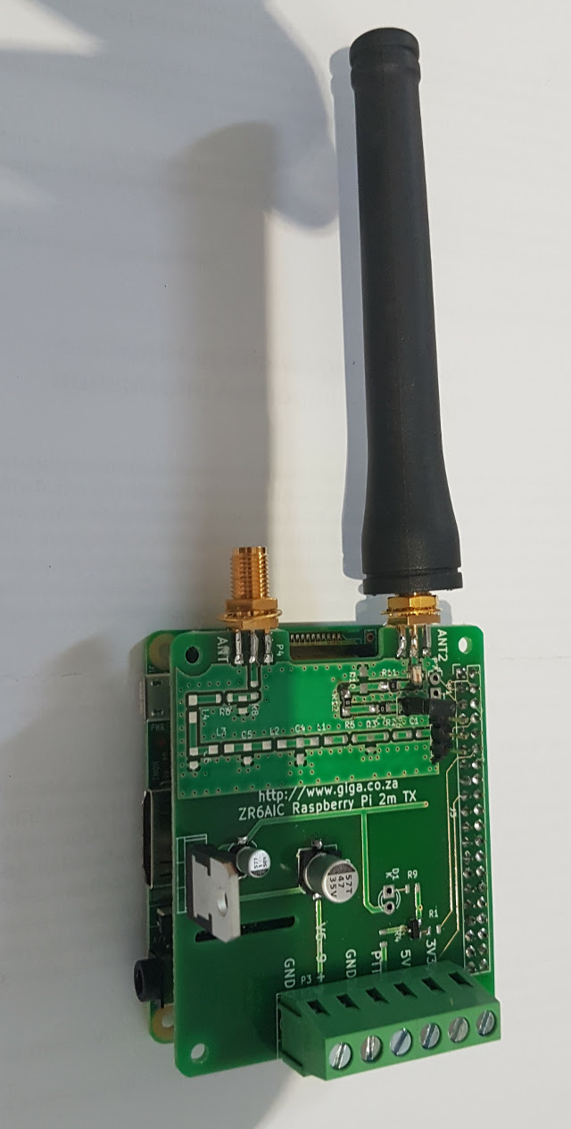
- There is a very nice library that will run on Raspberry Pi one B called rpitx witch can generate CW,SSB,FM SSTV...
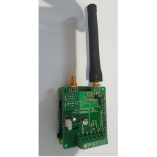
- Here is a image of a assembled Ceramic filter below, (this board is only avalible with Ceramic filter components in kit format.)
- This board allows you select one of two filter. (2 x SMA connectors one for each filter.
- The first filter is a seramic 2m low pass filter.
- The second filter can be build with band selectable componenets for a 7 stage low pass filter for the band you require.
- The Table below has teh calculated Vules for the componenets for the difren HF bands. (6m to 80m)
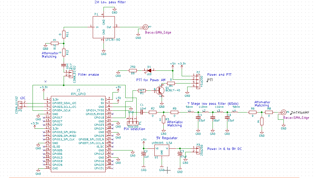
- The 2m seremic Low pass filter is componenet F1.
- R10,R11,R12 could be used as a impedance matching circuit or an attenuator. As I did not know what the expected output impedance would be of the Digital pin you can now match the impedance. (I use open shunt and 0 ohm in line for now until impedance can be measured.)
- The 7 stage low pass filter componenets consist of the followoing. (C4,C5,C6 and inductors L1,L2,L3,L4.
- I also added a input and output resistor matching circuit for the 7 stage low pass filter to match impedanses.
- The matching componenets for input is R2,R3,R5 and for output is R6,R7,R8. (I use open shunt and 0 ohm in line for now until impedance can be measured.)You could use it as atenuator if the signal is to big.
- I have added a PTT surcuite so that you can controle a PTT of a power Amp stage witch consits of R1, Q1, R4 with LED indicater.
- The PTT can be controlled with a digital pin on Raspberry Pi. ( I Do have a 2W external power amp Board available in build format)
- I also have added a low dropout 5V regulator so that you could power the board externaly without Raspberry pi from a battery. (U1 C2,C3)
- Yous hould be able to do APRS, QPRS, WSPR, RTTY, AFSK .... with this board.
- Modelation options is FM, AM ,SSB, SSTV.
Please note this is a kit with the Ceramic filter components for 2m meter only. Assembled kits will be avalible soon.
Link to my Blog describing how to use this board as a repeater with a dongle.
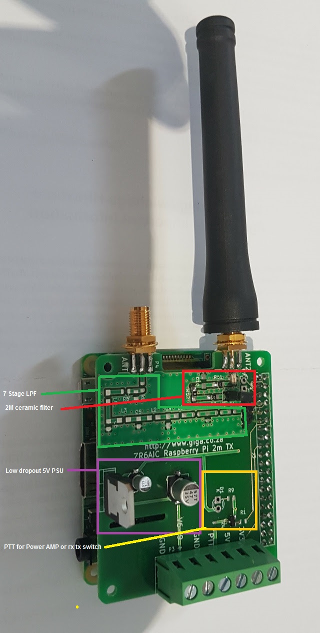
Rubber duck and Raspberry Pi is not included.
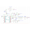
Circuit diagram for both filters.
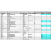
Componenet list.
The blue componenents are included in this kit.
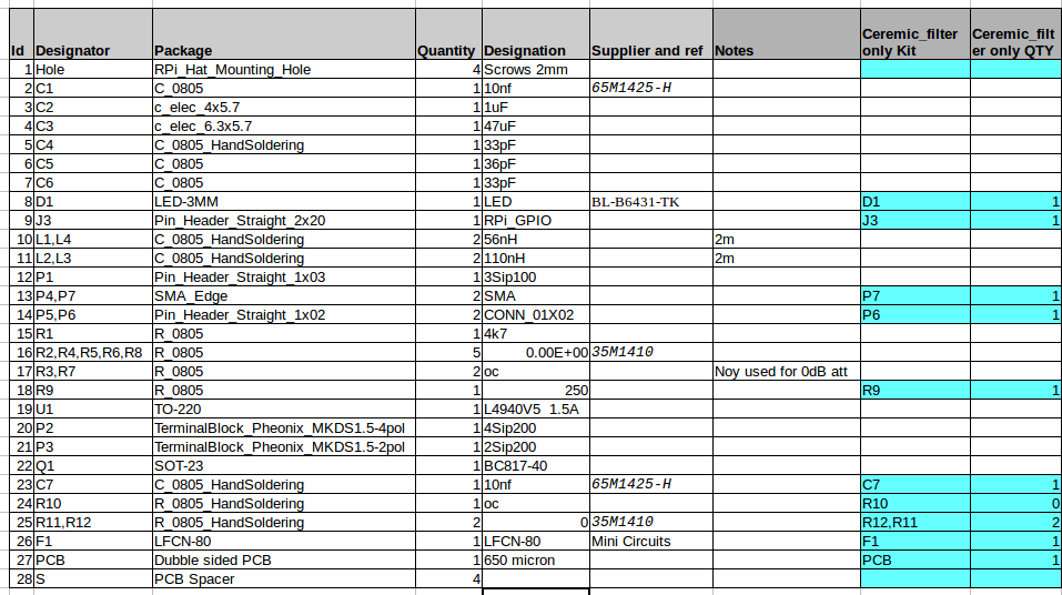
XSL spread sheet available here
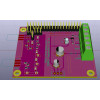
3D model of Board
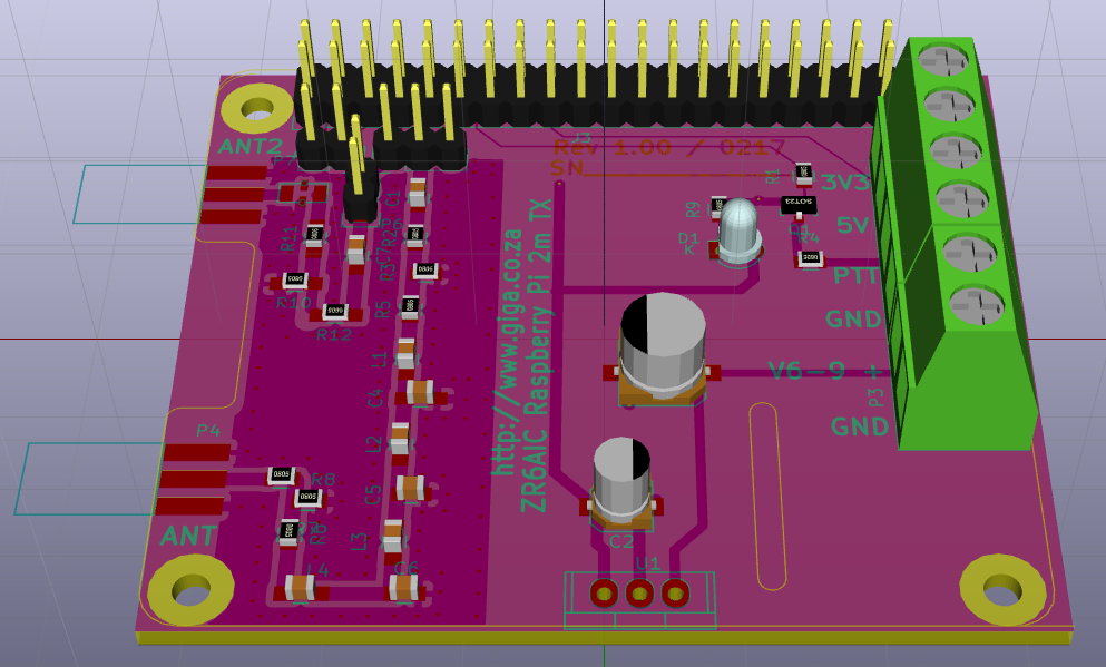
Filter values calculated in simulator. (SVCFilter)
HF Low pass filter values. Some values is not practical for the SMD footprints

Asembly Instructions. (manual prosess)
1) Start with all the Surface Mount components as the connectors and big components will get in the way of your heat gun.
2) Best way to assemble SM components is to place solder paste on the pads and then place the component on the solder past.
3) I use a hot air soldering iron to heat up the SM componenets with an low wind speed not to blow of the SM component.
4) When the Solder paste start melting remove the heat gun and the component should now be solderd.
5) I don't use SM components smaller than 0805 so that its still reasonably big to work with a tweezer.
6) Why SM componenents? When you are starting to work with componenets in the VHF and UHF and higher frequency band, the convention threw hole componenents are starting to affect the design and your design needs to compensate for that.
7) Conventional components is also bulky therefore the boards are bigger. So, to reduce the cost and and make a predictable design SM components is preferable
Link to my Blog describing how to use this board as a repeater with a dongle
Write a review
Your Name:Your Review: Note: HTML is not translated!
Rating: Bad Good
Enter the code in the box below:
Giga Technology © 2025

