Your shopping cart is empty!
Categories
- 3D Printing and Plastic peripherals (8)
- 433Mhz and Lora (9)
-
Amateur Radio (651)
- - Antenna Analyzer (12)
- - APRS (12)
- - ATU (5)
- - CW (1)
- - Digital Modes (9)
- - DMR (4)
- - Echolink (10)
- - Enclosure (13)
- - Eshail-2 (QO-100) (67)
- - GPS (8)
- - iGate (1)
- - Microcontrollers (43)
- - Microphone (1)
- - Power Supply (7)
- - Programming Cable (6)
- - QRP (9)
- - Radio interface (21)
- - Receiver (9)
- - Repeater (4)
- - RF Amplifiers (20)
- - RF Kits (19)
- - RF modules (116)
- - Rotator (1)
- - SDR (75)
- - Spectrum Analyzer (4)
- - SWR (9)
- - Transceiver (59)
- - WSPR (5)
- Antennas and Acc (320)
- Audio and Video (28)
- Bargain Box (1)
- Battery (3)
- Bluetooth (11)
- Cables (37)
- Computer Peripherals (104)
- Connectors (90)
- Data acquisition (1)
- Display (2)
- Electromechanical (25)
- Enclosure (12)
- GPS (6)
- Hardware (3)
- Home Automation (128)
- Inverter (9)
- Liquid (7)
- Lora (8)
- Microcontrollers (119)
- Modbus (3)
- MQTT (14)
- Network Radio (3)
- Networking (8)
- Power (133)
- Power supply (49)
- Radio Interface (17)
- RF Modules (142)
- ROIP (2)
- Satellite (93)
- Security (13)
- Sensor (17)
- Solar (14)
- Test and Measurements (66)
- Tools and Equipment (8)
- VOIP (10)
- Weather (1)
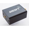
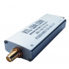
Ham It Up v1.3 - Listen to HF on Your RTL-SDR, No case Assembled PCB only (0.5MHz to 50MHz)
")
")
")
")
")
")
Price: R1,615.75
Ex Tax: R1,405.00
Ex Tax: R1,405.00
Qty:
- OR -
Add to Wish List
Add to Compare
Add to Compare

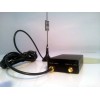
Upconverter in action with DVB Dongle (LO 125Mhz) (NooElec)
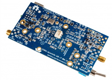
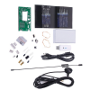
NooElec Ham It Up v1.3 - Listen to HF on Your RTL-SDR! Aluminum Enclosure, Silver (0.5MHz to 50MHz) Kompleet kt
Converts signals in the MF and HF Bands (0.5MHz to 50MHz) to signals in the VHF Band (125.5MHz to 175MHz) 125MHz version. Intended for use in receiver applications with projects like RTL-SDR/SDR# or FunCube Dongle.
KS4JU at HamRadioScience has a review of the board and has posted a tutorial video.
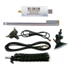
This Kit consist of the following.
- Upconverter with LO 125Mhz
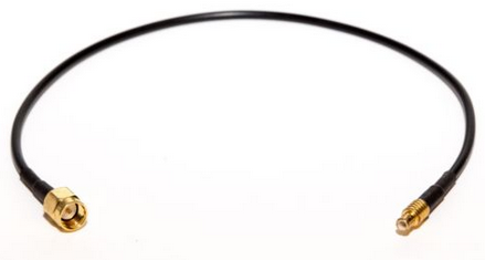
- Male MCX to Male SMA Pigtail Cable, RG174, 0.5 used to conect Upconverter to RTL dongle.
- RTL dongle is not included in this Kit
Major version changes (1.2 to 1.3):
- Input, output and LO filters reconfigured for substantial sensitivity and selectivity improvements
- New ultra low-noise linear power regulator (LP5907), with voltage noise under 10 µVRMS!
- Optional battery-powered operation for DXing on the go! (easy-to-assemble AAA battery holder sold separately, or roll-your-own solution with the easily-accessible battery power input vias)
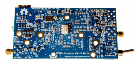
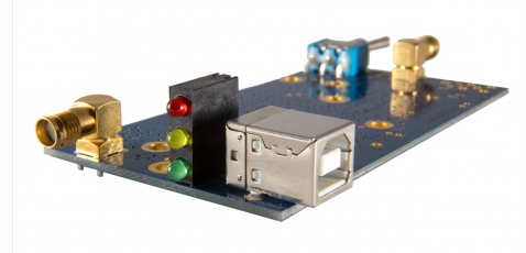
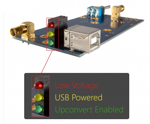
- New side-mount LED indicators, easily visible with or without an enclosure (Green = upconvert mode enabled; Yellow = USB powered; Red = low voltage)
- Fully-assembled broadband RF noise source built-in (Note: SMA output jack excluded to comply with government regulations, but can be purchased separately)
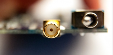
- u.FL socket (also known as IPX and UMCC) available for optional clock injection from an external clock source, should a higher-accuracy clock be desired
- 5 other u.FL socket mounting footprints for simplified testing, troubleshooting and demonstrational purposes
- Additional mounting holes to facilitate custom installations
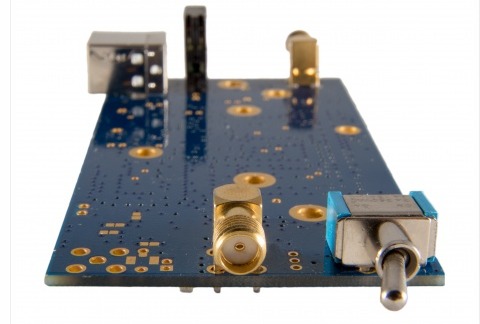
- Sturdy right-angle SMA connectors to improve spacing tolerances and ensure physical compatibility with our machined aluminum enclosures (enclosures sold separately)
- Redesigned for a surface-mount oscillator to eliminate potential oscillator-desocketing issues
IMPORTANT NOTE: due to changes implemented in v1.3, enclosures built for previous Ham It Up models are NOT 100% compatible. Specifically, new end-panels are required for full compatibility with older enclosures. Along with v1.3-specific enclosures, we also carry end-panel sets to allow for installation of Ham It Up v1.3 into older enclosures. If you cannot find these in our store, please contact us!
Standard features:
- Female SMA for both input and output for a wide array of connectivity options
- In-line SMA connectors. Much easier to connect and manipulate than side-by-side SMA connectors
- Antenna protection on RF input--in-circuit in both enable and passthrough mode--to protect your Ham It Up & SDR from stray ESD
- All critical components sourced exclusively from North American parts distributors
- Only ultra-low-noise components used in the signal path
- Ultra-high-Q, low ESR inductors and capacitors used for all filters
- Powered by a sturdy & common USB-B USB socket for a multitude of power input options
- RF-suitable power supply regulation (LP5907)
- PTC fuse on USB power input to protect your Ham It Up upconverter from short circuits
- Upconverter enable/passthrough toggle switch--less fiddling with small, delicate cables and connectors
- 125MHz oscillator for improved sensitivity (away from high-traffic RF zones, like broadcast FM)
- Stable <25ppm oscillator included
- LO disabled in passthrough mode
- A maximum input level of +1dBm with LO at +7dBm
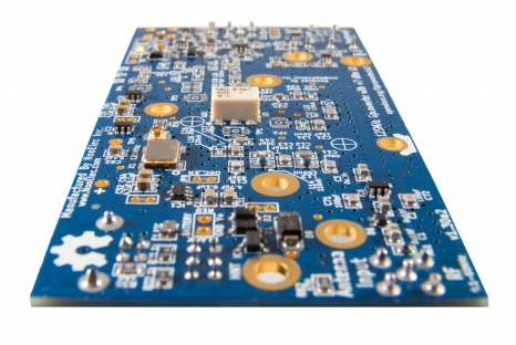
- High-quality 2-layer PCB with ENIG finish
- Small, light-weight PCB (just 3.8" x 1.9")
- Designed to fit standard off-the-shelf Hammond enclosures
- 7 mounting holes for standard PC screws
- Designed and manufacturered in conjunction with Opendous Inc., an excellent open-hardware design company
- Full project documentation--schematics, PCB design files, assembly information--is freely available.
- A portion of the proceeds from your purchase will be used to support this and other open-hardware, open-source initiatives
BONUS! We had space left on the PCB, so rather than waste it we have added a noise source circuit at no additional cost! We have even populated most of the components for you. We have the SMA connector required to complete this bonus noise source circuit available for a small additional fee. Details of the noise source circuit are available with the project documentation.
Operation:
Before operating your unit for the first time, and every time you run with a new SDR, we recommend running the tuning procedure located here. It is not a mandatory procedure but may help fine-tune your, erm. tuning. The basic operational instructions follow.
- Connect your antenna to the RF input
- Connect your SDR to the IF output
- Ensure your toggle switch is in the enable position
- Plug your USB power source into the USB-B USB jack
- Fire up your favorite SDR software. Tune to 125MHz + (+/- the tuning offset from the tuning procedure) + your desired frequency and enjoy!
The design files can be found in SVN or downloaded as an archive.
125MHz Upconverter Upconversion Losses
The 125MHz Upconverter has Upconversion Losses (data) of approximately 10dB from 0.1MHz to 55.8MHz and 15dB from 45kHz to 64.5MHz (data). The 1dB compression point is at +1dBm (this is the maximum input signal level before distortion occurs).
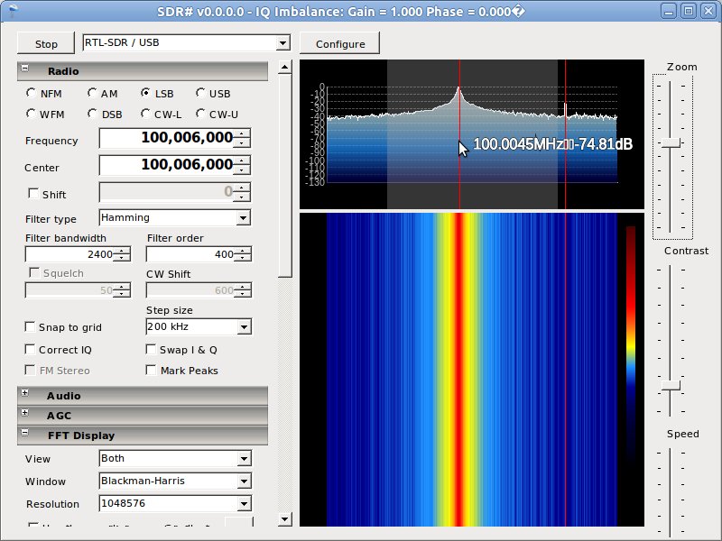
SDR Software Tuning Instructions
With your Upconverter input shorted or unconnected, tune your SDR software to several kHz above the Upconversion frequency ( 125.06MHz depending on version). Note where the nearest peak is (other than 1125.06MHz where you will see the DC spike) in the FFT display. This value takes into account any frequency offset from the Receiver/Demodulator. Since the 25ppm 125MHz oscillator is likely more precise than the Receiver/Demodulator, subtract the Upconversion frequency from the value to get the Receiver/Demodulator offset (in the picture below it would be 125.0045-125=0.0045). To tune to a Shortwave band such as 9.5MHz, simply add 9.5 to 125 and subtract the offset (9.5 + 125 - 0.0045 = 134.4955). With a high enough SDR sampling speed (0.5MSPS+) you will now be able to make out communication signals you can further tune to.
Please note the screenshot was done with the ould 100Mhz LO and not with 125 as in diskription
FAQ
It doesn't work! : Please first check all connections and try different cables. Then try a different USB power source (different port on PC, no hub). Then put the Upconverter into Upconvert mode and connect to your receiver tuned to 125.01MHz to see the LO bleed. You should be able to receive the 125MHz LO signal from the mixer which is about -45dBm at the IF/OUTput port.
I cannot receive any signals : If the above doesn't help, try a better/larger antenna. A quick hack is to connect the Upconverter INput to a large piece of safe exposed household metal such as a metal sink and its pipes or radiator. I recommend avoiding use of RF equipment during lightning storms or when lightning is forecast. You should be able to receive AM radio stations (0.5-2MHz) by tuning your receiver to 125.5-127MHz when connected to the Upconverter in Upconvert mode.
Can I connect two receivers to the same Upconverter? : Yes, but the two receivers must have inputs that are compatible with each other. The safest option is to make sure both receivers have no DC feed through a bias tee or disable this option. The receivers could damage each other if one or both have a DC bias. The output of the Upconverter is DC-Blocked so you do not need to worry about it unless dealing with high power levels (> +10dBm). SMA Splitter Adaptors can be found on eBay. Note the Upconverter uses SMA Jack (Female) connectors, not RP-SMA.
Why not add an amplifier to overcome the 10dB conversion loss? : Since the Noise Figure of an RF system is most dependent on the Noise Figure of the first elements in the signal chain, it does make sense to place an LNA at the antenna port. I just wasn't sure if most users would have their Upconverter at their antenna.
Can it be used for Transmitting? : Sure, there are no one-way paths in the Upconverter. If you have a VHF transmitter that operates in the 100MHz to 150MHz range then the Upconverter can be used in reverse as a down-converting mixer to broadcast over 0.5MHz to 50MHz (downconverted 100.5MHz to 150MHz signal). All you would need is a Power Amplifier and bandpass filter for your intended frequency range at the RF port and an attenuator at the IF port if the transmitting signal was above 0dBm.
Write a review
Your Name:Your Review: Note: HTML is not translated!
Rating: Bad Good
Enter the code in the box below:
Powered By OpenCart
Giga Technology © 2025
Giga Technology © 2025