Your shopping cart is empty!
Categories
- 3D Printing and Plastic peripherals (8)
- 433Mhz and Lora (9)
-
Amateur Radio (651)
- - Antenna Analyzer (12)
- - APRS (12)
- - ATU (5)
- - CW (1)
- - Digital Modes (9)
- - DMR (4)
- - Echolink (10)
- - Enclosure (13)
- - Eshail-2 (QO-100) (67)
- - GPS (8)
- - iGate (1)
- - Microcontrollers (43)
- - Microphone (1)
- - Power Supply (7)
- - Programming Cable (6)
- - QRP (9)
- - Radio interface (21)
- - Receiver (9)
- - Repeater (4)
- - RF Amplifiers (20)
- - RF Kits (19)
- - RF modules (116)
- - Rotator (1)
- - SDR (75)
- - Spectrum Analyzer (4)
- - SWR (9)
- - Transceiver (59)
- - WSPR (5)
- Antennas and Acc (320)
- Audio and Video (28)
- Bargain Box (1)
- Battery (3)
- Bluetooth (11)
- Cables (37)
- Computer Peripherals (104)
- Connectors (90)
- Data acquisition (1)
- Display (2)
- Electromechanical (25)
- Enclosure (12)
- GPS (6)
- Hardware (3)
- Home Automation (128)
- Inverter (9)
- Liquid (7)
- Lora (8)
- Microcontrollers (119)
- Modbus (3)
- MQTT (14)
- Network Radio (3)
- Networking (8)
- Power (133)
- Power supply (49)
- Radio Interface (17)
- RF Modules (142)
- ROIP (2)
- Satellite (93)
- Security (13)
- Sensor (17)
- Solar (14)
- Test and Measurements (66)
- Tools and Equipment (8)
- VOIP (10)
- Weather (1)
WIFI Wireless Transceiver Module Send Receive LWIP AP+STA A (ESP8266 Serial )
")
")
")
")
Price: R40.25
Ex Tax: R35.00
Ex Tax: R35.00
Qty:
- OR -
Add to Wish List
Add to Compare
Add to Compare

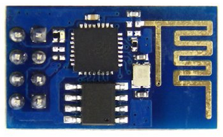
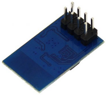
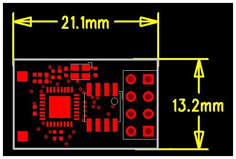
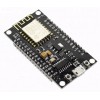
WIFI Wireless Transceiver Module Send Receive LWIP AP+STA A (ESP8266 Serial )
Integrated WEP, TKIP, AES, and WAPI engines.
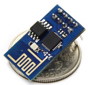
The ESP8266 is a highly integrated chip designed for the needs of a new connected world. It offers a complete and self-contained Wi-Fi networking solution, allowing it to either host the application or to offload all Wi-Fi networking functions from another application processor.
The ESP8266 has powerful on-board processing and storage capabilities that allow it to be integrated with the sensors and other application specific devices through its GPIOs with minimal development up-front and minimal loading during runtime. Its high degree of on-chip integration allows for minimal external circuitry, and the entire solution, including front-end module, is designed to occupy minimal PCB area.
Features
- SDIO 2.0, SPI, UART.
- 32-pin QFN package.
- Integrated RF switch, balun, 24dBm PA, DCXO, and PMU.
- Integrated RISC processor, on-chip memory and external memory interfaces.
- Integrated MAC/baseband processors.
- Quality of Service management.
- I2S interface for high fidelity audio applications.
- On-chip low-dropout linear regulators for all internal supplies.
- Proprietary spurious-free clock generation architecture.
- Integrated WEP, TKIP, AES, and WAPI engines.
Solutions
- Supports APSD for optimal VoIP applications
- Patented spurious noise cancellation algorithm for integration in SOC applications
- Supports Bluetooth co-existence interface
- Self-calibrated RF to ensure optimal performance under all operating conditions
- Zero factory tuning
- No external RF components
Specifications
- 802.11 b/g/n.
- Wi-Fi Direct (P2P), soft-AP.
- Integrated TCP/IP protocol stack.
- Integrated TR switch, balun, LNA, power amplifier and matching network.
- Integrated PLLs, regulators, DCXO and power management units.
- +19.5dBm output power in 802.11b mode.
- Power down leakage current of <10uA.
- Integrated low power 32-bit CPU could be used as application processor.
- SDIO 1.1/2.0, SPI, UART.
- STBC, 1 xl MIMO, 2x1 MIMO.
- A-MPDU & A-MSDU aggregation & 0.4ms guard interval.
- Wake up and transmit packets in < 2ms.
- Standby power consumption of < 1.0mW (DTIM3)
Help is some info to help your development.
ESP8266 Serial WIFI Module Communite Forum >> Detail about ESP8266
- High quality & low price
- LWIP agreement
- Support 3 modes: AP, STA, AP+STA
- Perfect and simple AT commands.
Package Included:
• ESP8266 Serial WIFI Wireless Transceiver Module Send Receive LWIP AP+STA
Here is some Information on the device
Software:
Software development kit for the device is avalible here ESP8266 IoT
Warnings: This module requires a 3.3 volt supply for VCC, and 3.3V logic.
It is not 5V tolerant. Connect RX or TX on 5V Arduino will destroy this module.
You must use a logic level converter, or a 3.3V Arduino
Arduino integration
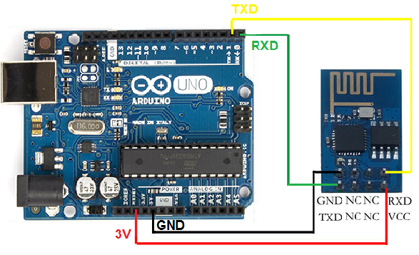
Now your Arduino can get on WiFI without braking the bank. Use this module for your next Interet of Things project, home automation, Or remote sensor project.
This module adats the ESP8226 IC for use over a serial connection using simple AT commands.
No SPI interface or Know-How is required.
Some info on what you can do.
First time use guide
Steps and note
- AT+RST restart the module, received some strange data, and "ready"
- AT+CWMODe=3 change the working mode to 3, AP+STA, only use the most versatile mode 3 (AT+RST may be necessary when this is done.)
Join Router
- AT+CWLAP search available wifi spot
- AT+CWJAP=“you ssid”, “password” join my mercury router spot
- AT+CWJAP=? check if connected successfully, or use AT+CWJAP?
TCP Client
- AT+CIPMUX=1 turn on multiple connection
- AT+CIPSTART=4,"TCP","192,168.1.104",9999 connect to remote TCP server 192.168.1.104 (the PC)
- AT+CIPMODE=1 optionally enter into data transmission mode
- AT+CIPSEND=4,5 send data via channel 4, 5 bytes length (see socket test result below, only "elect" received), link will be "unlink" when no data go through
TCP Server
- AT+CIPSERVER=1,9999 setup TCP server, on port 9999, 1 means enable
- AT+CIFSR check module IP address
- PC as a TCP client connect to module using socket test, send data
Here is some Example code for your Arduino.
You will need to add change the SSID and PASS verables in the code below for it to work.
#include <SoftwareSerial.h>
   #define SSID "xxxxxxxx"
   #define PASS "xxxxxxxx"
   #define DST_IP "220.181.111.85" //baidu.com
   SoftwareSerial dbgSerial(10, 11); // RX, TX
   void setup()
   {
     // Open serial communications and wait for port to open:
     Serial.begin(57600);
     Serial.setTimeout(5000);
     dbgSerial.begin(9600); //can't be faster than 19200 for softserial
     dbgSerial.println("ESP8266 Demo");
     //test if the module is ready
     Serial.println("AT+RST");
     delay(1000);
     if(Serial.find("ready"))
     {
       dbgSerial.println("Module is ready");
     }
     else
     {
       dbgSerial.println("Module have no response.");
       while(1);
     }
     delay(1000);
     //connect to the wifi
     boolean connected=false;
     for(int i=0;i<5;i++)
     {
       if(connectWiFi())
       {
         connected = true;
         break;
       }
     }
     if (!connected){while(1);}
     delay(5000);
     //print the ip addr
     /*Serial.println("AT+CIFSR");
     dbgSerial.println("ip address:");
     while (Serial.available())
     dbgSerial.write(Serial.read());*/
     //set the single connection mode
     Serial.println("AT+CIPMUX=0");
   }
   void loop()
   {
     String cmd = "AT+CIPSTART=\"TCP\",\"";
     cmd += DST_IP;
     cmd += "\",80";
     Serial.println(cmd);
     dbgSerial.println(cmd);
     if(Serial.find("Error")) return;
     cmd = "GET / HTTP/1.0\r\n\r\n";
     Serial.print("AT+CIPSEND=");
     Serial.println(cmd.length());
     if(Serial.find(">"))
     {
       dbgSerial.print(">");
       }else
       {
         Serial.println("AT+CIPCLOSE");
         dbgSerial.println("connect timeout");
         delay(1000);
         return;
       }
       Serial.print(cmd);
       delay(2000);
       //Serial.find("+IPD");
       while (Serial.available())
       {
         char c = Serial.read();
         dbgSerial.write(c);
         if(c=='\r') dbgSerial.print('\n');
       }
       dbgSerial.println("====");
       delay(1000);
     }
     boolean connectWiFi()
     {
       Serial.println("AT+CWMODE=1");
       String cmd="AT+CWJAP=\"";
       cmd+=SSID;
       cmd+="\",\"";
       cmd+=PASS;
       cmd+="\"";
       dbgSerial.println(cmd);
       Serial.println(cmd);
       delay(2000);
       if(Serial.find("OK"))
       {
         dbgSerial.println("OK, Connected to WiFi.");
         return true;
         }else
         {
           dbgSerial.println("Can not connect to the WiFi.");
           return false;
         }
       }
|
The 3.3V supply on the Arduino Uno has inadequate current capabilit to power this module.
You must provide a separate, higher 3.3V supply(about 300mA or better)
The ESP8225 module is very new on the market and support and documentation for it is currently very limited.
Write a review
Your Name:Your Review: Note: HTML is not translated!
Rating: Bad Good
Enter the code in the box below:


Powered By OpenCart
Giga Technology © 2025
Giga Technology © 2025