Your shopping cart is empty!
Categories
- 3D Printing and Plastic peripherals (8)
- 433Mhz and Lora (8)
- Support (2)
-
Amateur Radio (664)
- - Antenna Analyzer (12)
- - APRS (12)
- - ATU (5)
- - CW (1)
- - Digital Modes (9)
- - DMR (4)
- - Echolink (10)
- - Enclosure (14)
- - Eshail-2 (QO-100) (67)
- - GPS (9)
- - iGate (1)
- - Microcontrollers (43)
- - Microphone (1)
- - Power Supply (7)
- - Programming Cable (6)
- - QRP (9)
- - Radio interface (24)
- - Receiver (11)
- - Repeater (4)
- - RF Amplifiers (20)
- - RF Kits (20)
- - RF modules (118)
- - Rotator (1)
- - SDR (77)
- - Spectrum Analyzer (4)
- - SWR (9)
- - Transceiver (60)
- - WSPR (5)
- Antennas and Acc (322)
- Audio and Video (28)
- Aviation (4)
- Bargain Box (1)
- Battery (3)
- Bluetooth (11)
- Cables (37)
- Computer Peripherals (104)
- Connectors (93)
- Data acquisition (1)
- Display (2)
- Electromechanical (26)
- Enclosure (13)
- GPS (7)
- Hardware (4)
- Home Automation (128)
- Inverter (9)
- Liquid (7)
- Lora (8)
- Microcontrollers (121)
- Modbus (3)
- MQTT (14)
- Network Radio (3)
- Networking (9)
- Power (135)
- Power supply (49)
- Radio Interface (17)
- RF Modules (144)
- ROIP (5)
- Satellite (95)
- Security (13)
- Sensor (17)
- Solar (14)
- Test and Measurements (66)
- Tools and Equipment (8)
- Tracking (4)
- VOIP (13)
- Weather (1)
6M Dipole antenna with Balun Center 54MHz


Price: R916.55
Ex Tax: R797.00
Ex Tax: R797.00
Qty:
- OR -
Add to Wish List
Add to Compare
Add to Compare

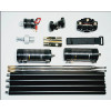
6M Band Dipole antenna with Balun 1:1 200w max Center 54 MHz
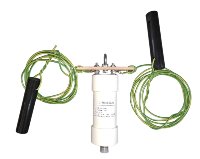
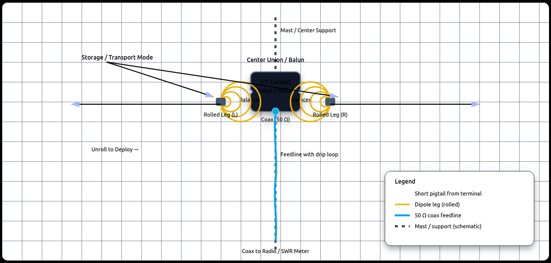
Deployments covered: Horizontal dipole and Inverted‑V.
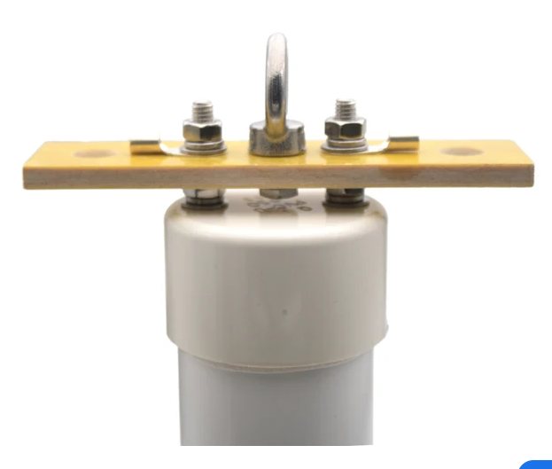
Center balun: 1:1 current balun, 50 Ω unbalanced to 50 Ω balanced, 1–56 MHz, 200 W, waterproof (e.g., DYKB 1:1 HF).
Target frequency: 6M band 52Mhz
6 m Dipole Antenna Manual (52 MHz)
Parts & Tools You’ll Need
Antenna hardware
- Two lengths of wire (cut to calculated lengths below)
- Balun (recommended 1:1 at the feedpoint)
- e.g., Durable 160m‑6m Bands 500w Waterproof HF Balun 1:1 Universal
- (covers 1.8 – 54 MHz, weatherproof)
- Center insulator (or mounting plate for balun)
- End insulators (plastic or ceramic)
- Coaxial feedline (50 Ω coax)
- Rope or cord for supports
- Shackles/eyebolts
Tools
- Wire cutters/strippers
- Tape measure (metric)
- Crimp/ solder tools
- Antenna analyzer or SWR meter
Tuning & Testing
-
Power up your rig with a dummy load to test coax continuity.
-
Connect an antenna analyzer or SWR meter.
-
Sweep through the 52 MHz region; look for lowest SWR.
-
If resonant frequency is too low (SWR high):
-
Shorten each leg slightly (~1–2 cm at a time).
-
-
If resonant frequency is too high:
-
Lengthen legs (if adjustable with rope, hang a bit lower temporarily).
-
-
Aim for SWR < 1.5:1 at your target frequency.
Tip: Always trim wires a little at a time — you can cut more, but you can’t add wire back without re-splicing.
Deployment Tips & Best Practices
✔ Keep the balun weather sealed (self-vulcanizing tape or outdoor enclosure).
✔ Maintain symmetry — unequal leg lengths raise SWR and distort pattern.
✔ Avoid nearby metal structures — move the antenna outward.
✔ Raise the antenna higher for better DX performance.
✔ Document your lengths and angles for future reference.
Quick Reference Summary
| Configuration | Leg Length (each) | Total Span | Typical Impedance |
|---|---|---|---|
| Horizontal | ~1.38 m | ~2.75 m | ~70–75 Ω |
| Inverted V (90°) | ~1.31 m | ~2.62 m | ~50 Ω |
Safety
Install antennas well clear of power lines.
Use insulated supports or rope if metal structures are nearby.
Write a review
Your Name:Your Review: Note: HTML is not translated!
Rating: Bad Good
Enter the code in the box below:
Powered By OpenCart
Giga Technology © 2026
Giga Technology © 2026