Your shopping cart is empty!
Categories
- 3D Printing and Plastic peripherals (8)
- 433Mhz and Lora (9)
-
Amateur Radio (651)
- - Antenna Analyzer (12)
- - APRS (12)
- - ATU (5)
- - CW (1)
- - Digital Modes (9)
- - DMR (4)
- - Echolink (10)
- - Enclosure (13)
- - Eshail-2 (QO-100) (67)
- - GPS (8)
- - iGate (1)
- - Microcontrollers (43)
- - Microphone (1)
- - Power Supply (7)
- - Programming Cable (6)
- - QRP (9)
- - Radio interface (21)
- - Receiver (9)
- - Repeater (4)
- - RF Amplifiers (20)
- - RF Kits (19)
- - RF modules (116)
- - Rotator (1)
- - SDR (75)
- - Spectrum Analyzer (4)
- - SWR (9)
- - Transceiver (59)
- - WSPR (5)
- Antennas and Acc (320)
- Audio and Video (28)
- Bargain Box (1)
- Battery (3)
- Bluetooth (11)
- Cables (37)
- Computer Peripherals (104)
- Connectors (90)
- Data acquisition (1)
- Display (2)
- Electromechanical (25)
- Enclosure (12)
- GPS (6)
- Hardware (3)
- Home Automation (128)
- Inverter (9)
- Liquid (7)
- Lora (8)
- Microcontrollers (119)
- Modbus (3)
- MQTT (14)
- Network Radio (3)
- Networking (8)
- Power (133)
- Power supply (49)
- Radio Interface (17)
- RF Modules (142)
- ROIP (2)
- Satellite (93)
- Security (13)
- Sensor (17)
- Solar (14)
- Test and Measurements (66)
- Tools and Equipment (8)
- VOIP (10)
- Weather (1)
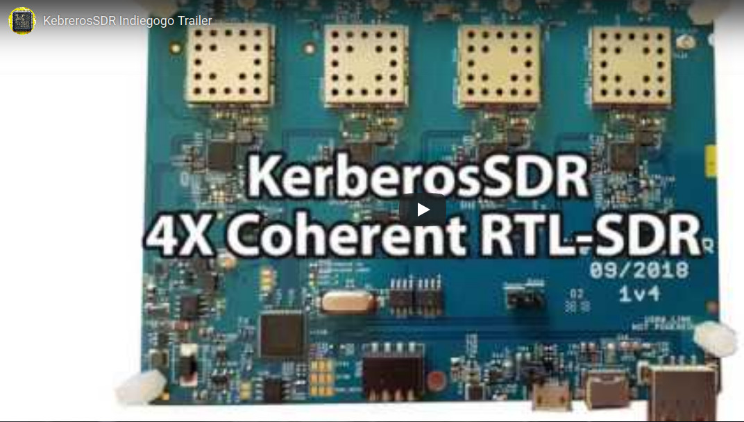
KerberosSDR - 4 Channel Coherent RTL-SDR (Direction Finding)
")
")
")
")
")
")
Price: R5,592.45
Ex Tax: R4,863.00
Ex Tax: R4,863.00
Qty:
- OR -
Add to Wish List
Add to Compare
Add to Compare

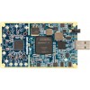
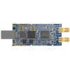
KerberosSDR - 4 Channel Coherent RTL-SDR (Direction Finding)
A Coherent RTL-SDR with 4x Channels. For direction finding, passive radar, beam forming, or just as four RTL-SDRs!
The RTL-SDR software defined radio phenomenon has changed the world by unlocking low cost access to the radio spectrum. Whilst RTL-SDR is now a relatively mature commodity item that almost everyone whose tinkered with electronics has played with, there is still so much more potential to be unlocked.
A phase coherent RTL-SDR can be made out of two or more RTL-SDR dongles that share a common clock. With a bit of help from a noise source, the RTL-SDRs can be synced together. Once synced interesting applications become available, such as direction finding, beam forming and passive radar.
Phase coherent RTL-SDRs have been worked on and demonstrated several times over the past few years, but at RTL-SDR.com we've been disappointed to find that so far there hasn't been any easy way to replicate these experiments.
The required hardware has been difficult to build and access, and the software has been kept as unreleased closed source or has been too complicated to install and use.
With the Kerberos SDR we aim to change that by making phase coherent applications easier to access and run by providing ready to use hardware and good demo software with an open source DSP code base that can be extended.
Please note, although we are aiming to make KerberosSDR as easy to use as possible, at least a basic to moderate level of computer and radio technical knowledge is required, or you must be willing to learn. This is an experimental product and some willingness to experiment and explore solutions is required. The demo software that we provide is capable of doing direction finding and 2-RX passive radar. Your own custom code or applications will be required for custom applications.
Most KerberosSDR content has been posted to RTL-SDR.COM:
KerberosSDR Quickstart Guide: rtl-sdr.com/ksdr
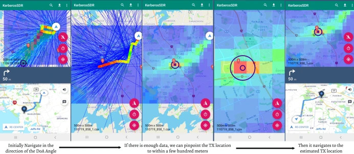
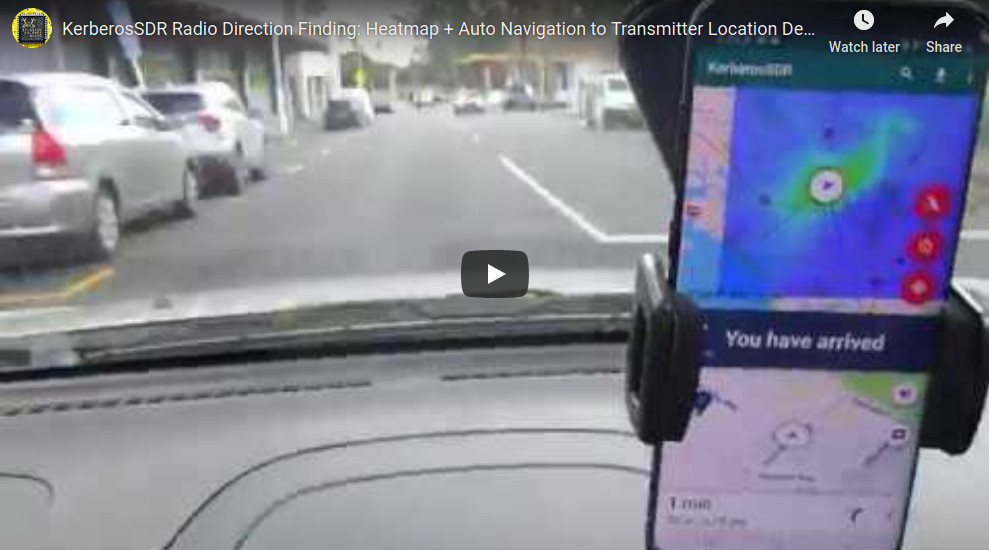
KerberosSDR Direction Finding Android App Demo: rtl-sdr.com/kerberossdr-app-update-heatmap-precise-tx-localizing-turn-by-turn-navigation-demo-videos
KerberosSDR Direction Finding Android App Tutorial: rtl-sdr.com/kerberossdr-direction-finding-with-android-app-demo-and-tutoria
KerberosSDR SingalsEverywhere Video: rtl-sdr.com/signalseverywhere-kerberossdr-direction-finding-video-tutorial
KerberosSDR Networked Direction Finding with RDFMapper: rtl-sdr.com/networked-radio-direction-finding-with-kerberossdr-and-rdfmapper
KerberosSDR Passive Radar Traffic Statistics: rtl-sdr.com/measuring-traffic-in-a-neighborhood-with-kerberossdr-and-passive-radar
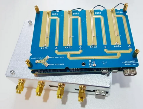
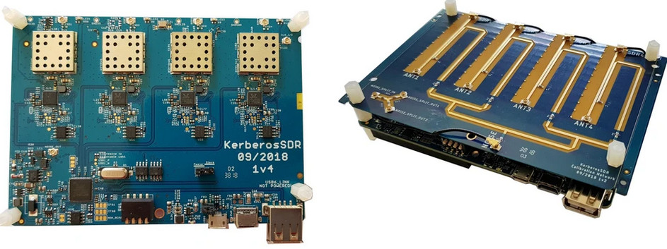
What's Included?
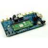
- he KerberosSDR Board which has:
- 4x RTL-SDR R820T2 Receivers
- A wideband noise source that can be switched in software
- USB Hub so only one USB connection is required
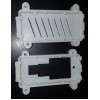
- A calibration board for synchronizing samples with the noise source
- A shielded metal enclosure
- Internal cables for connecting the two boards and noise source
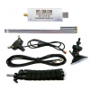
What you'll need to provide: You'll need to provide your own antennas for your application (e.g. four magnetic whips for direction finding, two directional antennas for passive radar), a 5V USB power supply, a microUSB USB cable, and a Linux computing device like a PC/laptop or single board computer like a Raspberry Pi 3/4 or Tinkerboard. (Must run Linux natively - VMs have too much USB lag for coherency).
KerberosSDR Hardware Specs.
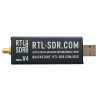
Each RTL-SDR on board the KerberosSDR is based on the R820T2 and RTL2832U chips, which are the same chips used in the most common RTL-SDR dongles.
- Frequency Range: 24 MHz - 1.7 GHz
- ADC Sample Rate: 2.4 MSPS
- Bit Depth: 8 Bits
KerberosSDR connects it's RTL-SDRs to the calibration board via four u.FL cables. The calibration board then has four u.FL -> SMA cables that can be used to connect to antennas.
Please note that antennas are not included with the KerberosSDR. For direction finding applications you'll need four omni-directional antennas (e.g. magnetic whips). For passive radar you'll require two directional antennas.
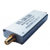
Power Requirements
The KerberosSDR takes a USB power input. Any 3A supply should be sufficient. On some modern PCs you may even be able to directly power the board without any additional power supply. ***The previous version of KerberosSDR included microUSB for data and a USB-C connector for power. The USB-C connector is superior to the microUSB, but we had not implemented the USB-C specification. This caused a great deal of confusion, which is why all current KerberosSDR include two microUSB connectors.
Applications
Some applications might include:
- Pinpointing the source of VHF/UHF noise, pirates, interference, jammers, unknown signals etc using radio direction finding (RDF)
- Using passive radar to monitor aircraft that do not transmit ADS-B
- Monitoring vehicle or marine traffic with passive radar
- Direction finding for amateur radio fox hunts
- Determining the location of rescue or stolen asset beacons
- Combining multiple small dishes to create a large dish for radio astronomy via beam forming.
- Using the four tuners as standard RTL-SDRs. e.g. two for trunking, one for ADS-B and one for weather satellites.
KerberosSDR Demo Software.
For development of the open source DSP software we have hired Tamás Peto, a PhD student at Budapest University of Technology and Economics. He has developed an excellent open source Linux demo application that can be used for direction finding and passive radar. The DSP and synchronization code could easily be extended to implement other applications, or extend features.
The code can be found at https://github.com/rtlsdrblog/kerberossdr, and a guide to installing it can be found at www.rtl-sdr.com/ksdr. A support forum is available at https://www.rtl-sdr.com/forum/viewforum.php?f=9.
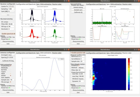
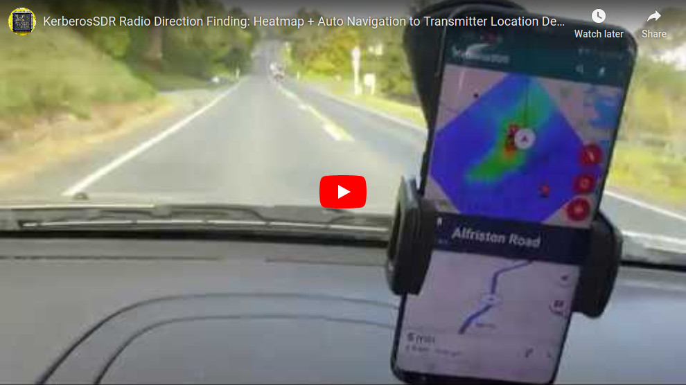
KerberosSDR Direction Finding
Our open source demo software developed by Tamás Peto gives us a graph and compass display that shows the measured bearing towards the transmitter location. The measured bearing is relative to the antenna array, so we simply convert it by taking the difference between the car's bearing (determined approximately via road direction and landmarks in Google Earth) and the measured bearing.
By combining angle data with our companion Android App, it is possible to drive around with the direction finding system and very accurately pinpoint the location of an RF transmitter.
Android App Download: https://play.google.com/store/apps/details?id=com.rtlsdr.realtimebearing
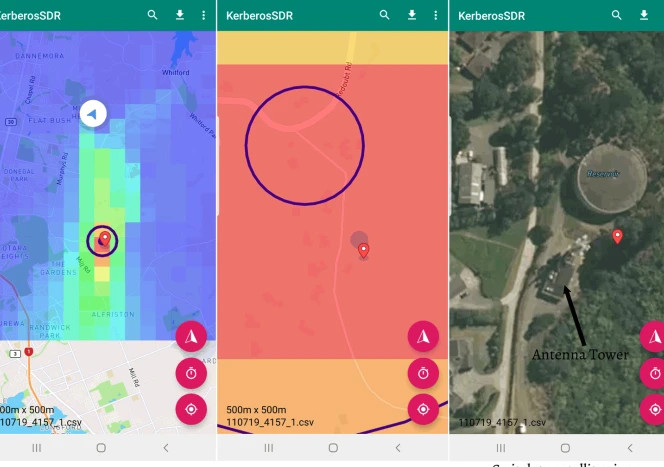
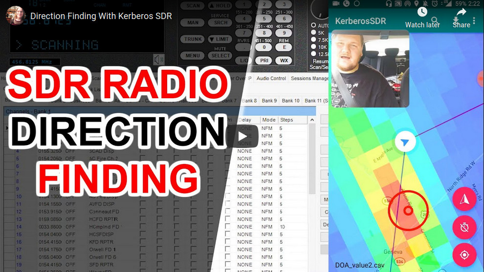
415Mhz signal detection within 100m
Below is a demo video created by Harold of the SignalsEverywhere YouTube channel. He shows how easy it is to use the KerberosSDR and Android App to locate a P25 transmitter within 15 minutes of drive time.
Below are three demonstrations.

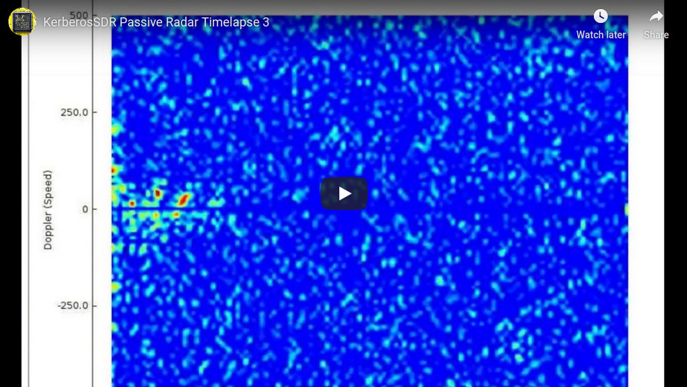
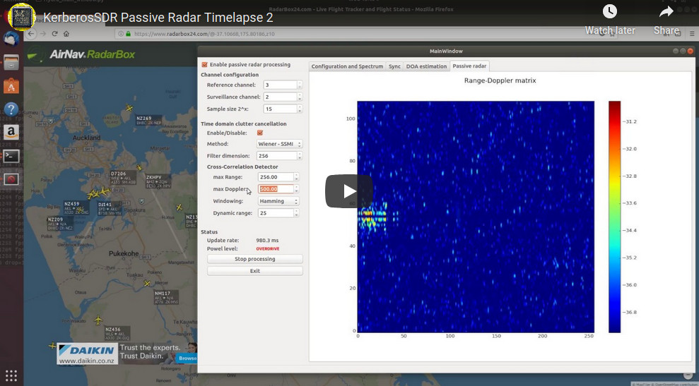
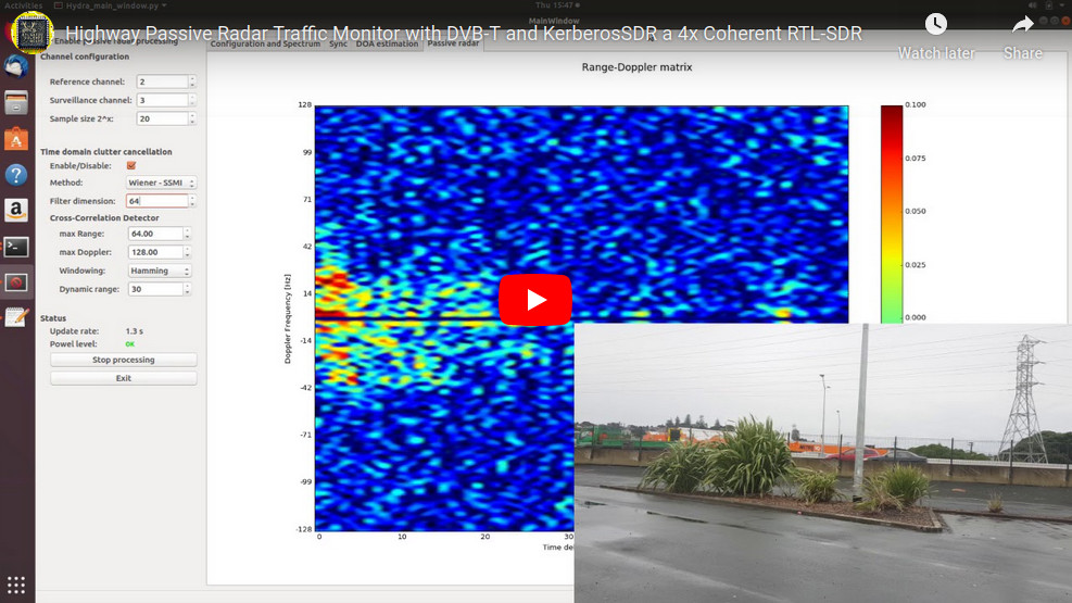
KerberosSDR Passive Radar.
KerberosSDR can also be used for passive radar. Normal radar systems work by transmitting a pulse of RF energy, and listening to the reflections from objects like planes, cars and ships. Passive radar works by using already existing transmitters such as those for FM/TV and listening for reflections that bounce of objects.
With a simple passive radar system you need two directional antennas and two coherent receivers. One antenna points at the transmitting 'reference' tower, and the other at the 'surveillance' area where you want to listen for reflections. It's important to try and keep as much of the reference signal out of the surveillance antenna as possible, which is why directional antennas like Yagi's are used.
The result is a Doppler vs time delay graph, where the reflection of aircraft, cars, ships and other objects can be seen. The Doppler gives you the speed of the object relative to your antenna and the transmitting tower, and the time delay gives you the distance relative to your antenna and the transmitter tower.
Powering and Connecting the Hardware

Your KerberosSDR should already come fully assembled.
As there are four on board RTL-SDRs, KerberosSDR has fairly high power requirements. A single USB 3.0 port on a computer that can handle up to 3A is enough to power the device from one high quality USB cable. Note that only the microUSB port is connected to the computers USB port and that the USB-C port is only for additional power.
If you only have USB 2.0 hardware, or cannot provide 3A from the USB port (e.g. single board PCs cannot provide this much current), then you'll need to plug a second power source into the USB-C port on the KerberosSDR. USB-C is used for the dedicated power port as it has much less voltage drop, and the cables are generally higher quality. This power source should be an plugged into a wall 5V USB supply or external 5V battery if going portable.
Note that the USB-C port will not activate for high voltage "power delivery" (PD) USB-C power supplies, such as those used with laptops. It will only work on normal 5V power supplies.
Antenna 1 is the port to the left. You can confirm this by looking at the DIP switches. The writing on the DIP switches indicates the antenna order.
40 Pin Header
Please note that this header is experimental only and we are not supporting use of this feature at the moment.
It is designed for powering a Raspberry Pi. If you connect a Raspberry Pi to the header, and power the KerberosSDR you can power it this way. But you must have a very good power supply for the KerberosSDR.
Raspberry Pi/Single Board Computer (SBC) Ready to Use Images
We strongly recommend running your KerberosSDR on a Pi 3/4 or Tinkerboard and using these ready to use images. Other platforms like Linux PCs, and other SBCs do work, but it will be difficult to provide support for other platforms as there are too many variables. At least test your unit on these platforms first.
Download the appropriate .img file below, unzip it, and burn it to an 8GB or larger SD Card for your SBC using Win32DiskImager or Etcher.
Powering and Connecting the Hardware
Your KerberosSDR should already come fully assembled.
As there are four on board RTL-SDRs, KerberosSDR has fairly high power requirements. A single USB 3.0 port on a computer that can handle up to 3A is enough to power the device from one high quality USB cable. Note that only the microUSB port is connected to the computers USB port and that the USB-C port (Batch 1), or the right USB micro (Batch 2 or newer) is only for additional power.
If you only have USB 2.0 hardware, or cannot provide 3A from the USB port (e.g. single board PCs cannot provide this much current), then you'll need to plug a second power source into the USB-C port (Batch 1)/right USB micro (Batch 2 or newer), on the KerberosSDR. This power source should be an plugged into a wall 5V USB supply or external 5V battery if going portable. The supply should be able to deliver 2.4A.
Note that the USB-C port on batch 1 units will not activate for high voltage "power delivery" (PD) USB-C power supplies, such as those used with laptops. It will only work on normal 5V power supplies.
BATCH 2 USB CHANGES (BATCH 2 SHIPPING SINCE FEB 1 2019):
Please note the USB-C port shown in the image below has been replaced with a microUSB port on batch 2 and newer productions.
Due to too many people having issues finding USB-C supplies that work, batch 2 reverts to microUSB on the power port. If you purchased after FEB1 2019, you will have a batch 2 unit.
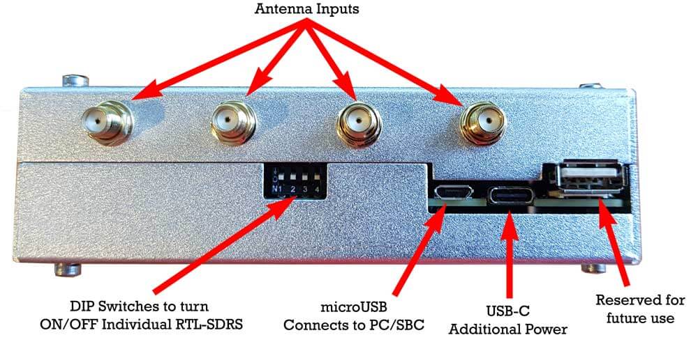
Antenna 1 is the port to the left. You can confirm this by looking at the DIP switches. The writing on the DIP switches indicates the antenna order.
40 Pin Header
Please note that this header is experimental only and we are not supporting use of this feature at the moment.
It is designed for powering a Raspberry Pi. If you connect a Raspberry Pi to the header, and power the KerberosSDR you can power it this way. But you must have a very good power supply for the KerberosSDR.
Raspberry Pi/Single Board Computer (SBC) Ready to Use Images
We strongly recommend running your KerberosSDR on a Pi 3/4 or Tinkerboard and using these ready to use images. Other platforms like Linux PCs, and other SBCs do work, but it will be difficult to provide support for other platforms as there are too many variables. At least test your unit on these platforms first.
Download the appropriate .img file below, unzip it, and burn it to an 8GB or larger SD Card for your SBC using Win32DiskImager or Etcher.
On your SBCs, it is important to make sure thermal throttling is not occurring (via appropriate heatsinking/fans on the SBC if needed) otherwise sample loss, and hence coherent lock failure may occur.
Raspberry Pi 3 / 4
External WiFi AutoConnect Hotspot: KerberosAndroid
External WiFi AutoConnect Password: KerberosAndroid
External WiFi IP Address: Check WiFi Hotspot Device for assigned IP
Internal WiFi Hotspot: KerberosPi
Internal WiFi Password: KerberosPi
Internal WiFi IP Address: 192.168.4.1 (for VNC, web interface and Android App)
VNC & Linux Username: pi
VNC & Linux Password: raspberry
Internal Hotspot Address for Web Control: IP_ADDR:8080/init
Internal Hotspot Address for Android App: IP_ADDR:8081
Update Notes: Only the latest IMG V1.5 & 1.6 works on the Pi 4. IMG1.6 fixes long term sync stability on the Pi 4, upgrades the web UI, add PR peak hold & improves update rates significantly. 1.6.1 Fixes a HTML bug on the passive radar web display.
Download IMG 1.6.1: https://drive.google.com/open?id=1DhCLYv99QHwpJRM2gvG6UtrIM1RO8_Ua
Download IMG V1.6: https://drive.google.com/open?id=1MK9OiGCznLAv8hENDZoOMKl_F0_GYCZs
Download IMG V1.5: https://drive.google.com/file/d/14AVWcNOKr6wyBtfkwIBFqNrN3d9xAweA/view?usp=sharing
Download IMG V1.4: https://drive.google.com/file/d/1H77bUt9AXVZC8NXvcl0cBubuh9yuMTti/view?usp=sharing
Download IMG V1.3: https://drive.google.com/file/d/1Vwt-bcQNDP6KEWtqdadOdZOT-LBGQXhj/view?usp=sharing
Tinkerboard
External WiFi AutoConnect Hotspot: KerberosAndroid
External WiFi AutoConnect Password: KerberosAndroid
External WiFi IP Address: Check WiFi Hotspot Device for assigned IP
Internal WiFi Hotspot: Kerberos_Tinker
Internal WiFi Password: kerberos
Internal WiFi IP Address: 192.168.4.1 (for VNC, web interface and Android App)
Linux Password: kerberos
Default Internal Hotspot IP address for VNC: IP_ADDR:5900 (no password)
Address for web control: IP_ADDR:8080/init
Address for Android App: IP_ADDR:8081
Download IMG V1.4: https://drive.google.com/open?id=1shO-9xD2prrqGBSg9Zjj5tVCighqPg3p
Download IMG V1.3: https://drive.google.com/file/d/1Btter1AWNWV0VCnXqfosu5E0V6E3RTXO/view?usp=sharing
Note please see our current issues forum thread for any currently known issues.
More information for other Embedit or or pc cyctem follow the link here https://www.rtl-sdr.com/ksdr/
Write a review
Your Name:Your Review: Note: HTML is not translated!
Rating: Bad Good
Enter the code in the box below:
Powered By OpenCart
Giga Technology © 2025
Giga Technology © 2025